
A high-voltage charging circuit for controlling adaptive regulation of pulses

A technology of self-adaptive adjustment and high-voltage charging, applied in the field of medical devices, can solve the problem that the defibrillator cannot achieve the optimal charging effect, and achieve the effect of optimizing the charging process and fast charging

Active Publication Date: 2018-12-18
SHAANXI QINMING MEDICAL CO LTD +1
View PDF5 Cites 2 Cited by
  • Summary
  • Abstract
  • Description
  • Claims
  • Application Information

AI Technical Summary

Problems solved by technology

When the transformer and load are determined, the working mode of the flyback switching power supply is determined by the frequency and duty cycle of the pulse signal that controls the on-off of the switch tube; and the adjustment of the control pulse is usually by using mature pulse width modulation (PWM) technology or pulse Frequency modulation (PFM) technology, but neither of them can make the flyback switching power supply always work in a critical state, so when it is used in a defibrillator, it cannot achieve the best charging effect

Method used


Image

  • A high-voltage charging circuit for controlling adaptive regulation of pulses
  • A high-voltage charging circuit for controlling adaptive regulation of pulses
  • A high-voltage charging circuit for controlling adaptive regulation of pulses

Examples


Embodiment Construction

[0018] The present invention will be described in further detail below in conjunction with the accompanying drawings.

[0019] In the embodiment, the power supply voltage Vdc is set to be 5.0V, and the target charging voltage Vc1 of the energy storage capacitor is set to be 800V.

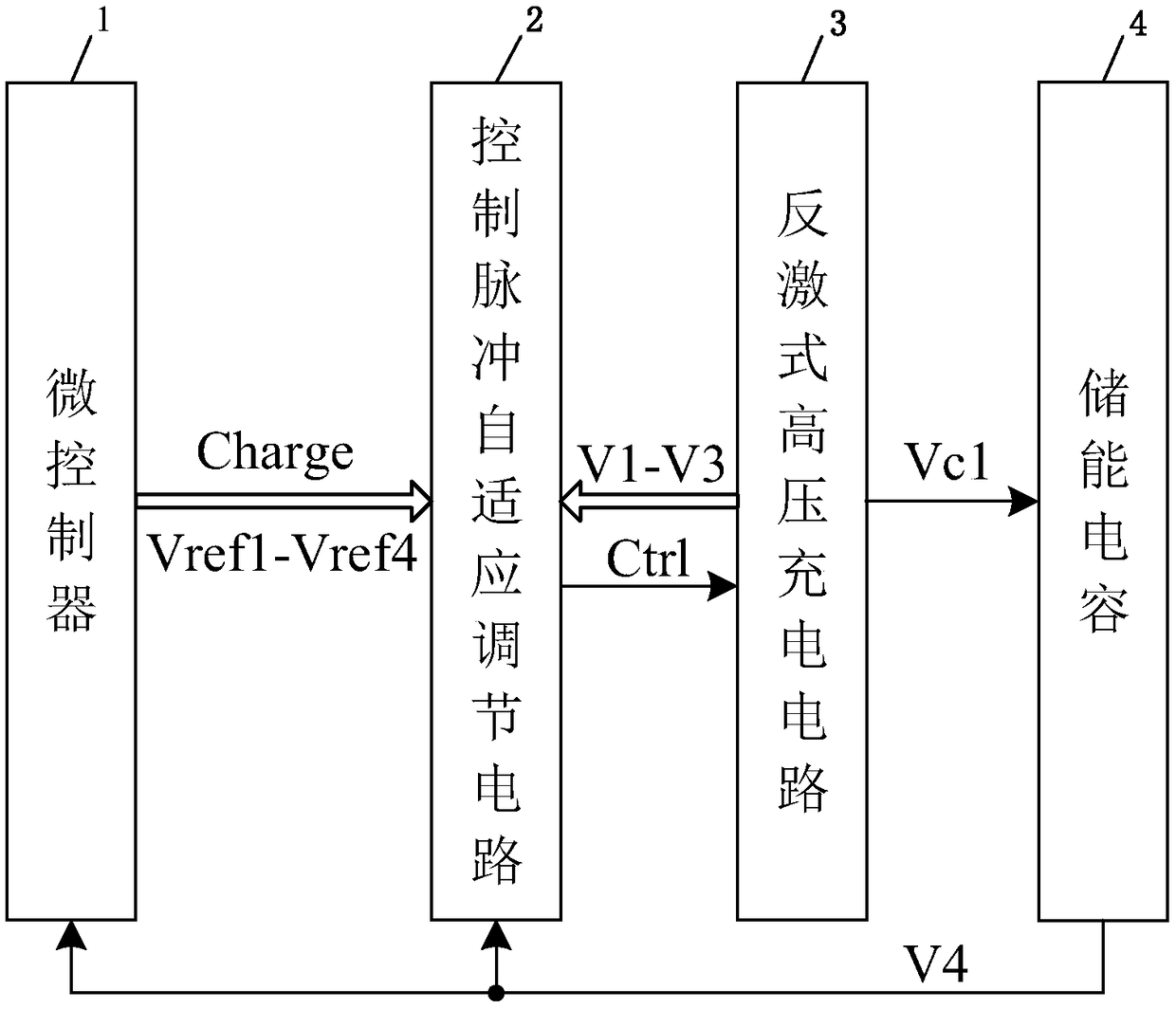
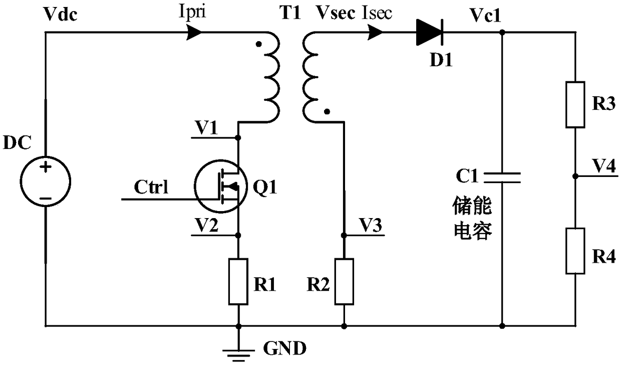
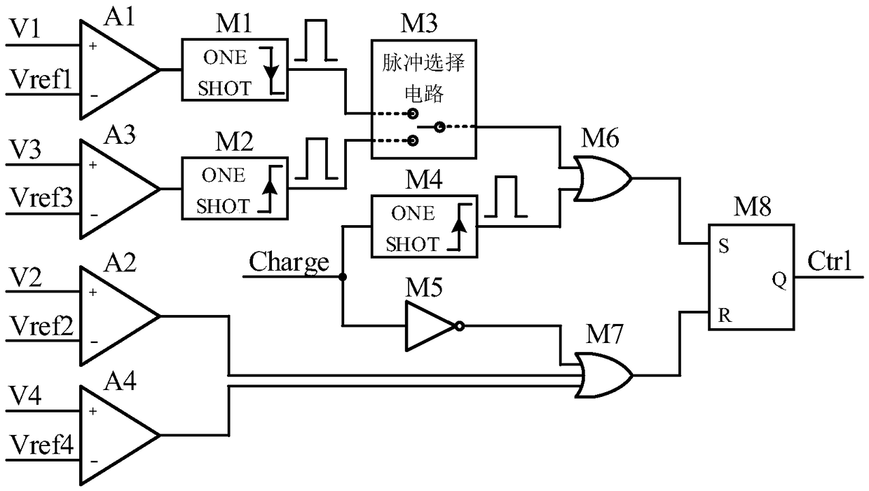
[0020] see figure 1 , The hardware circuit of the present invention is composed of four modules: a microcontroller 1, a control pulse adaptive adjustment circuit 2, a flyback high-voltage charging circuit 3 and an energy storage capacitor 4. The microcontroller outputs the charging control signal Charge, and when Charge becomes high level / low level, charging starts / stops. Microcontroller 1 outputs reference voltages Vref1-Vref4 through digital-to-analog conversion or control of the reference voltage source. The value of Vref1 is Vdc+20mV=5.02V, the value of Vref2 is 100mV, the value of Vref3 is -250mV~-10mV, and the value of Vref4 is is 2V. In addition, the microcontroller 1 monitors the feedback...


PUM


Abstract

A high voltage charging circuit for controlling adaptive regulation of pulses comprises a microcontroller, a pulse adaptive regulation controlling circuit, a flyback high-voltage charging circuit andan energy storage capacitor, wherein the energy storage capacitor is used for storing high-voltage energy, and the microcontroller can output a charging control signal and a plurality of reference voltages to the control pulse adaptive regulating circuit and detect the feedback voltage of the energy storage capacitor in real time; The control pulse adaptive regulating circuit can compare the multi-channel feedback voltages of the flyback high voltage charging circuit and the energy storage capacitor with the corresponding reference voltages output by the microcontroller, output pulse control signals after analyzing by the logic control circuit, and control the on-off of the flyback high voltage charging circuit; and the control pulse adaptive regulating circuit can regulate the on-off of the flyback high voltage charging circuit. The flyback high voltage charging circuit is used for charging the energy storage capacitor. The charging process is optimized, the energy storage capacitor can be charged efficiently and quickly, and the high-voltage charging circuit is suitable for an implantable defibrillator or an external defibrillator and other occasions requiring high-voltage charging.

Description

technical field [0001] The invention belongs to the field of medical devices, and in particular relates to a high-voltage charging circuit for self-adaptive regulation of control pulses. Background technique [0002] Sudden cardiac death is a serious threat to human life and has become a global public health problem due to its high incidence and high mortality. Ventricular fibrillation is the main cause of sudden cardiac death, and the only effective way to terminate ventricular fibrillation is to use electric shock defibrillation within a short time after the occurrence of ventricular fibrillation. Currently, clinical defibrillation technologies include implantable defibrillators and external defibrillators, both of which use high-voltage, high-current pulses for defibrillation. The high-voltage charging circuit is one of the core modules of the defibrillator hardware circuit. This module needs to increase the low voltage of the power supply battery to a high voltage and s...

Claims


Application Information

Patent Timeline
IPC IPC(8): H02J7/00
CPCH02J7/0036H02J7/007
Inventor 王建飞邬小玫黄彦淇金华
Owner SHAANXI QINMING MEDICAL CO LTD
Learn More