User equipment for wireless communication, method and apparatus in a base station

A technology for user equipment and wireless communication, applied in wireless communication, radio transmission system, transmission modification based on link quality, etc. Effect

Active Publication Date: 2018-12-18
SHANGHAI LANGBO COMM TECH CO LTD
View PDF5 Cites 19 Cited by
  • Summary
  • Abstract
  • Description
  • Claims
  • Application Information

AI Technical Summary

Problems solved by technology

[0004] The inventor found through research that specially designing the uplink control information format and allocating periodic time-frequency resources for sending beam restoration requests will bring about complex system implementation, delay in sending requests, and problems of air interface resource overhead

Method used


Image

  • User equipment for wireless communication, method and apparatus in a base station
  • User equipment for wireless communication, method and apparatus in a base station
  • User equipment for wireless communication, method and apparatus in a base station

Examples


Embodiment 1

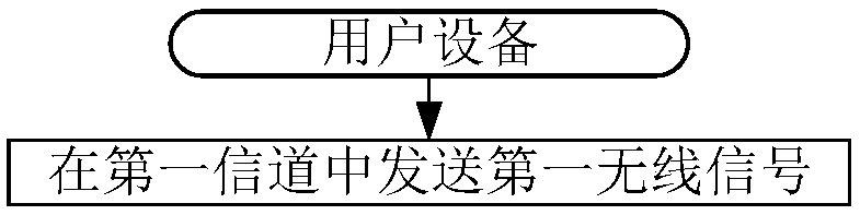
[0164] Embodiment 1 illustrates the flow chart of the first wireless signal according to the present application, as shown in the attached figure 1 shown. attached figure 1In , each box represents a step. In Embodiment 1, the user equipment in this application sends a first wireless signal in a first channel. Wherein, the first bit block and the second bit block are used by U2 to generate the first wireless signal, the bits in the second bit block are a subset of the bits in the third bit block, and the second bit block The sending of is determined by the user equipment itself; the first bit block consists of X1 bits, the second bit block consists of X2 bits, the third bit block consists of X3 bits, the A maximum of X4 bits can be accommodated in the first channel; the X1 is a positive integer smaller than the X4, the X3 and the X4 are respectively a positive integer greater than 1, and the X2 is a positive integer less than or equal to the X3 An integer; if the sum of the...

Embodiment 2

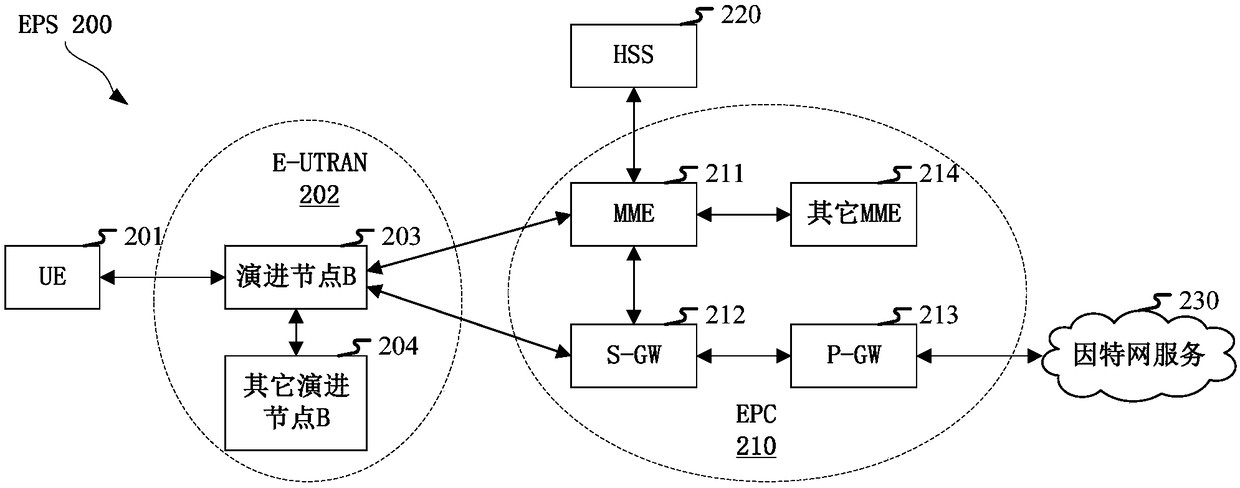
[0181] Embodiment 2 illustrates a schematic diagram of a network architecture according to the present application, as attached figure 2 shown. figure 2 It is a diagram illustrating LTE (Long-Term Evolution, long-term evolution), LTE-A (Long-Term Evolution Advanced, enhanced long-term evolution) and a future 5G system network architecture 200 . The LTE network architecture 200 may be called EPS (Evolved Packet System, evolved packet system) 200 . EPS 200 may include one or more UE (User Equipment, User Equipment) 201, E-UTRAN (Evolved UMTS Terrestrial Radio Access Network) 202, EPC (Evolved Packet Core, Evolved Packet Core) 210, HSS (Home Subscriber Server, Home Subscriber Server) 220 and Internet Services 230. Among them, UMTS corresponds to Universal Mobile Telecommunications System (Universal Mobile Telecommunications System). The EPS may be interconnected with other access networks, but these entities / interfaces are not shown for simplicity. As shown, the EPS provide...

Embodiment 3

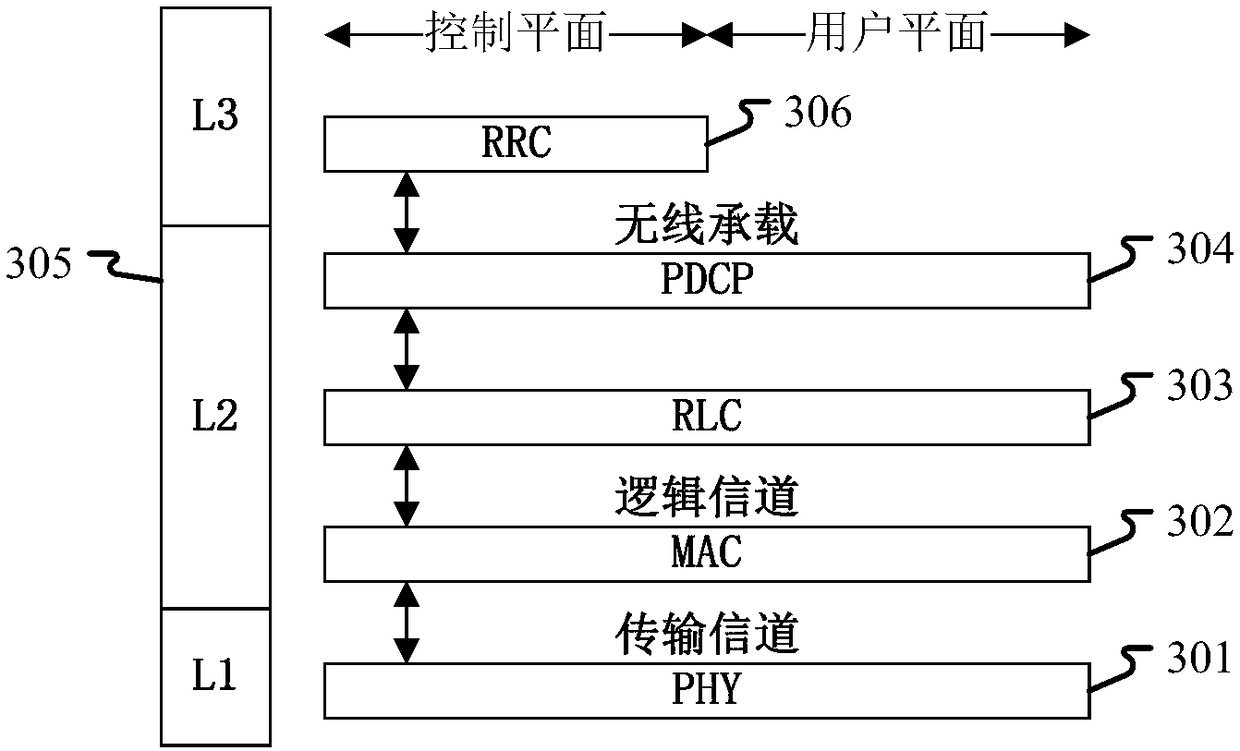
[0187] Embodiment 3 shows a schematic diagram of an embodiment of a wireless protocol architecture of a user plane and a control plane according to the present application, as shown in the attached image 3 shown. image 3 is a schematic diagram illustrating an embodiment of a radio protocol architecture for a user plane and a control plane, image 3 The radio protocol architecture for UE and eNB is shown with three layers: Layer 1, Layer 2 and Layer 3. Layer 1 (L1 layer) is the lowest layer and implements various PHY (Physical Layer) signal processing functions. The L1 layer will be referred to herein as PHY 301 . Layer 2 (L2 layer) 305 is above PHY 301 and is responsible for the link between UE and eNB through PHY 301 . In the user plane, the L2 layer 305 includes a MAC (Medium Access Control, Media Access Control) sublayer 302, an RLC (Radio Link Control, Radio Link Layer Control Protocol) sublayer 303, and a PDCP (Packet Data Convergence Protocol, packet data Convergen...


PUM


Abstract

The invention discloses a piece of user equipment for wireless communication, a method and an apparatus in a base station. The user equipment transmits a first radio signal in a first channel, a firstbit block and a second bit block are used to generate the first radio signal, bits in the second bit block are a subset of bits in a third bit block, and transmission of the second bit block is determined by the user equipment itself. The invention has the advantages of simplifying the system realization of user-triggered reporting, improving the channel utilization efficiency, increasing the probability of user-triggered reporting, and controlling the air interface resource overhead.

Description

technical field [0001] The present application relates to a wireless signal transmission scheme in a wireless communication system, in particular to a multi-antenna transmission method and device. Background technique [0002] Massive MIMO (Multi-Input Multi-Output) has become a research hotspot in the next generation of mobile communication. In massive MIMO, multiple antennas use beamforming to form narrower beams pointing in a specific direction to improve communication quality. [0003] In the 3GPP (3rd Generation Partner Project, 3rd Generation Partnership Project) discussion on the new air interface, some companies proposed that the user equipment should measure the service beam during the communication process. When the quality of the service beam is found to be poor, the uplink physical layer control channel It is used for the user equipment to send a beam recovery request (Beam Recovery Request) to the base station, and the base station then changes the serving beam...

Claims


Application Information

Patent Timeline
Patent Type & Authority Applications(China)
IPC IPC(8): H04W72/04H04B7/06H04L1/00H04L5/00
CPCH04B7/0617H04L1/0027H04L5/0048H04W72/046H04B7/0486H04B7/0632H04W72/0453H04W72/0446H04W72/23
Inventor 张晓博
Owner SHANGHAI LANGBO COMM TECH CO LTD
Why Eureka
Try Eureka