
A heat-dissipating strip of a PTC heat-sensitive material heat-dissipating device and a manufacturing method and use thereof

A technology for heating devices and heat-sensitive materials, applied in the direction of heating element materials, heating element shapes, ohmic resistance heating parts, etc. Improve comfort and environmental protection functions, improve heat dissipation area and heat, and improve the effect of the use environment

Inactive Publication Date: 2018-12-18
SUZHOU GUOWEI CERAMIC ELECTRICAL APPLIANCE CO LTD
View PDF12 Cites 0 Cited by
  • Summary
  • Abstract
  • Description
  • Claims
  • Application Information

AI Technical Summary

Problems solved by technology

[0005] Purpose of the invention: This invention aims at the fact that the S-shaped heat sinks and trapezoidal ribs of the traditional heat dissipation strips cannot be formed and produced in batches, and it is impossible to avoid the need to make them fully fit with the solder pieces to ensure that they will not be opened or desoldered during vacuum welding. Defects such as low strength and poor welding caused by deformation and twisting of the upper and lower fixing sheets holding the corrugated strips, high manufacturing costs, easy desoldering, and poor bonding strength between heat dissipation corrugations and heat conduction sheets, provide A heat dissipation strip of a heat-generating device of a PTC heat-sensitive material

Method used


Image

  • A heat-dissipating strip of a PTC heat-sensitive material heat-dissipating device and a manufacturing method and use thereof
  • A heat-dissipating strip of a PTC heat-sensitive material heat-dissipating device and a manufacturing method and use thereof
  • A heat-dissipating strip of a PTC heat-sensitive material heat-dissipating device and a manufacturing method and use thereof

Examples


Embodiment 1

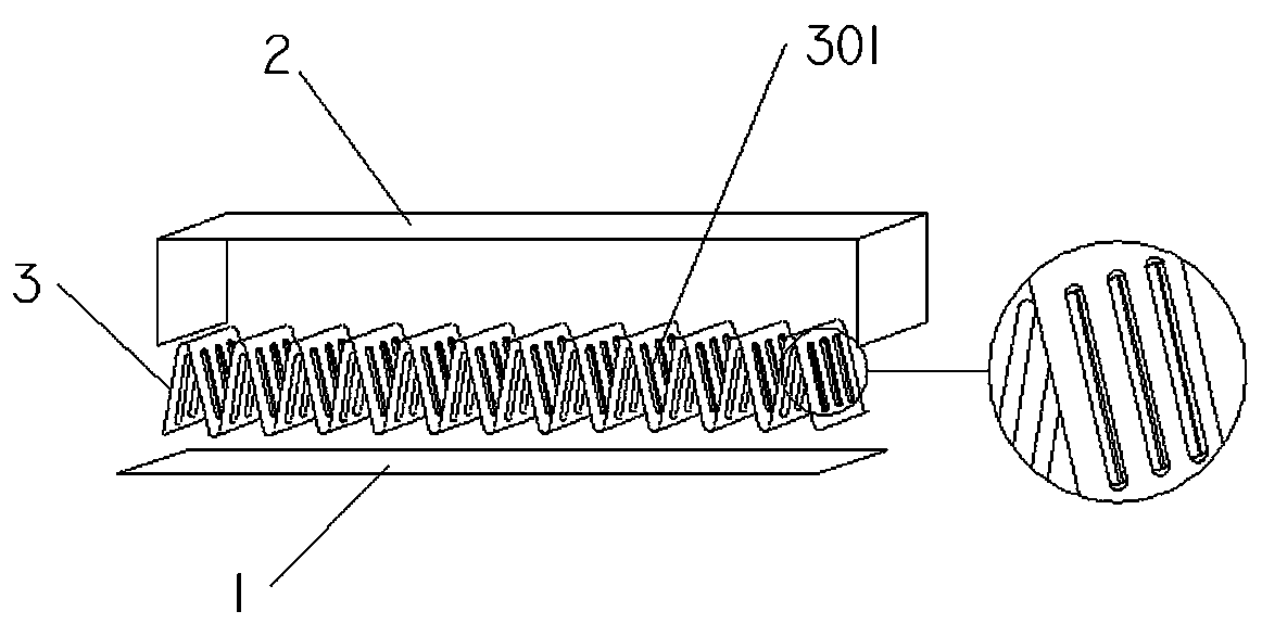
[0050] Such as figure 1 The heat dissipation strip of the PTC heat-sensitive material heating device shown includes a heat dissipation corrugation 3 clamped by a heat conduction flat sheet 1 and a folded edge positioning heat conduction sheet 2, and the heat dissipation corrugation 3 has a height direction of not less than A semi-arc concave surface 301, the concave surface 301 is perpendicular to the width direction of the heat dissipation strip.

Embodiment 2

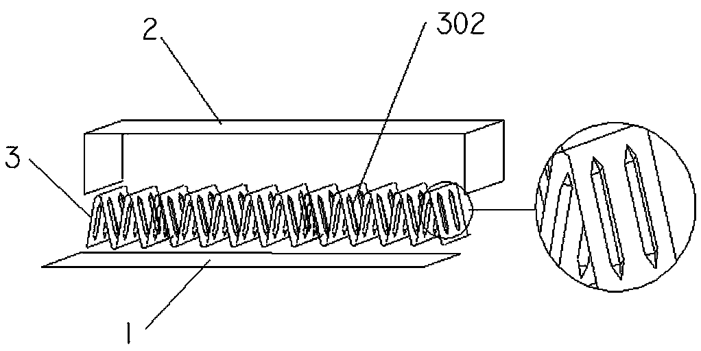
[0052] Such as figure 2 As shown, referring to Embodiment 1, the heat dissipation corrugations 3 have not less than one angled surface 302 along the height direction of the heat dissipation surface, and the angled surface 302 is perpendicular to the width direction of the heat dissipation strip.

Embodiment 3

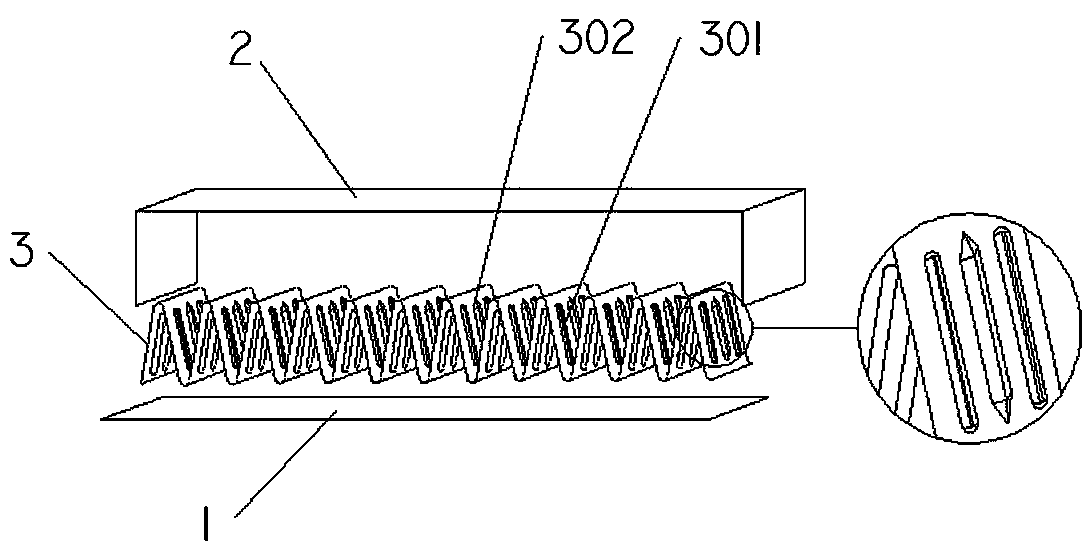
[0054] Such as image 3 As shown, referring to Embodiments 1 and 2, the height direction of the heat dissipation corrugation 3 has a concave surface 301 and a fan-folded surface 302 at the same time, and the concave surface 301 and the angled surface 302 are perpendicular to the width direction of the heat dissipation strip.


PUM


Abstract

The invention discloses a heat-dissipating strip of a PTC heat-sensitive material heat-dissipating device, comprising a heat-dissipating ripple clamped by a heat-conducting flat fin and a folded edgepositioning heat-conducting fin, wherein the heat-dissipating ripple is provided with not less than a half-arc concave surface or a folded corner surface or simultaneously has a half-arc concave surface and a folded corner surface along the height direction of the heat-dissipating surface. At the same time, the invention also discloses a special tool for the heat dissipation strip, a manufacturingmethod, a PTC heat-sensitive material heating device and an electric appliance using the heat dissipation strip. A heat dissipation corrugated surface of the present invention is designed so that a small amount of water droplets can be accumulated and contained in a concave or corner surface, With the instantaneous heating of the heating device, the micro-condensate droplets are heated and volatilized immediately, thus effectively improving the service environment, enhancing the strength of the heat sink bar and PTC heater, and improving the service reliability and environmental protection function of the PTC heater and the electric appliance.

Description

technical field [0001] The invention belongs to the technical field of heat-sensitive ceramic manufacturing, in particular to a heat dissipation strip of a PTC heat-sensitive material heating device, a preparation method and application thereof. Background technique [0002] Patented sealed positive temperature coefficient thermistor heater, patent number 200620034186, the corrugation is S-shaped, although it is beneficial to improve condensation, but the S-shaped heat sink and trapezoidal ribs cannot be mass-molded and produced, even if the samples are made by hand or 3D. , and it is impossible to avoid deformation, twisting and other low strength and welding due to the need to make it fully bonded to the soldering piece to ensure that it does not open or desolder during vacuum welding and pressurizes the upper and lower fixing pieces that hold the corrugated strip. bad defect. [0003] In addition, such as the patented corrugated heat dissipation strip, the patent No. 201...

Claims


Application Information

Patent Timeline
Patent Type & Authority Applications(China)
IPC IPC(8): H05B3/02H05B3/14H05B3/40
CPCH05B3/02H05B3/141H05B3/40
Inventor 蒋国屏王洁奇
Owner SUZHOU GUOWEI CERAMIC ELECTRICAL APPLIANCE CO LTD
Learn More