
Fluidized bed cluster reactor

A fluidized bed and reactor technology, applied in the field of gas-solid reaction fluidization equipment, can solve the problems of not describing the fluidized bed cluster reactor, unable to meet practical application requirements, affecting the gas-solid reaction efficiency, etc., and achieve easy implementation. , Reasonable design, small particle wear effect

Active Publication Date: 2018-12-21
QINGDAO UNIV OF SCI & TECH
View PDF13 Cites 0 Cited by
  • Summary
  • Abstract
  • Description
  • Claims
  • Application Information

AI Technical Summary

Problems solved by technology

Therefore, the current gas-solid fluidized reactors (such as fluidized bed reactors, etc.) have problems such as large pressure loss and serious wear of particulate materials, which lead to low gas-solid reaction efficiency, high energy consumption, and high cost. It is urgent to develop pressure loss Gas-solid fluidized reactor with small particle material wear
[0003] At present, the research on the large pressure loss of the reactor is still in the preliminary exploration stage. Some researchers try to change the porosity of the adsorption bed in the reactor to reduce the pressure drop, but the effect is very small and affects the gas-solid reaction efficiency.
In view of the severe wear of granular materials, some researchers have tried to develop materials with high wear resistance, but these materials with high wear resistance are still in the research stage and are expensive, which cannot meet the needs of practical applications.
None of the prior art describes the fluidized bed cluster reactor of the present invention

Method used


Image

  • Fluidized bed cluster reactor
  • Fluidized bed cluster reactor
  • Fluidized bed cluster reactor

Examples


Embodiment 1

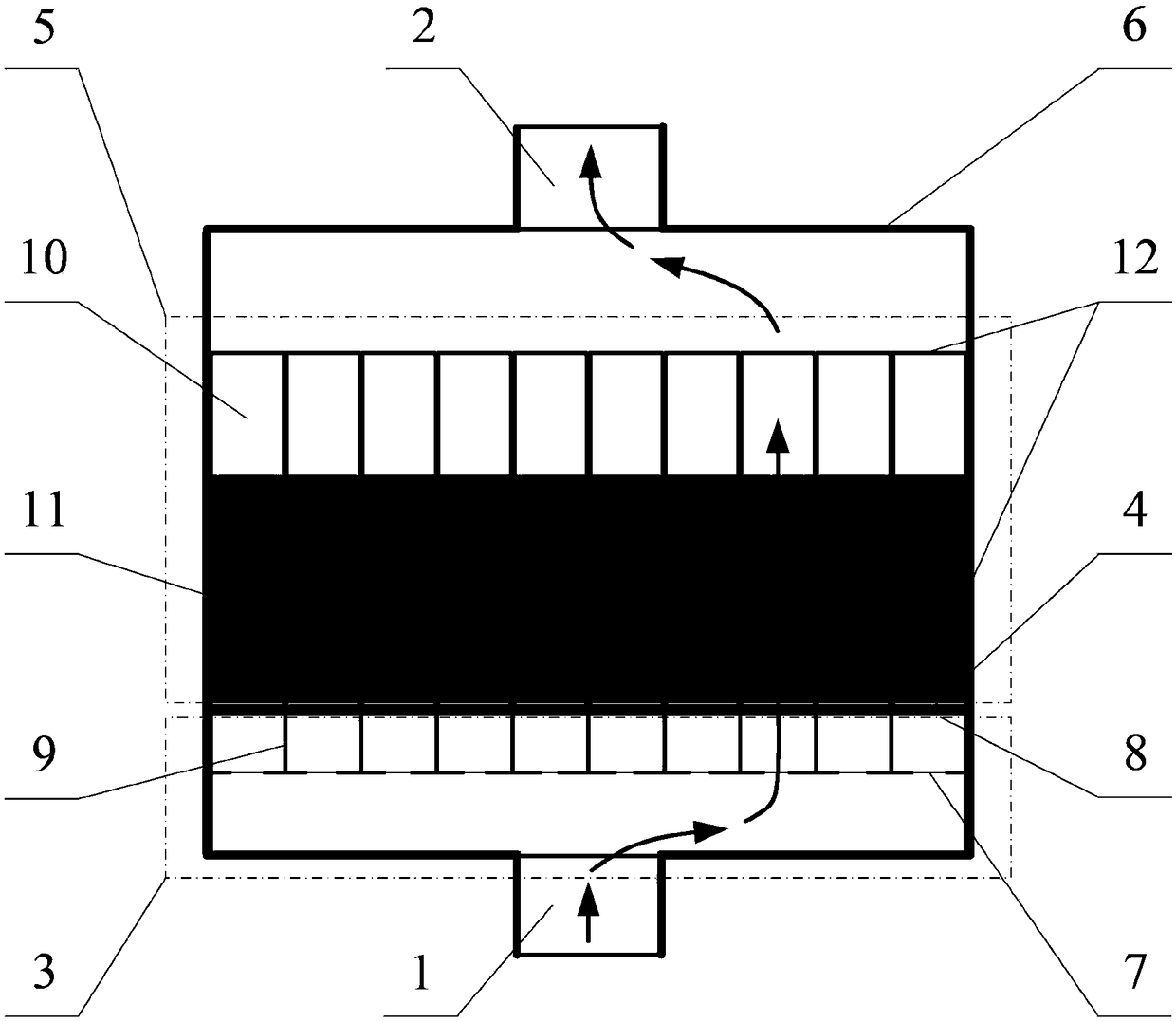
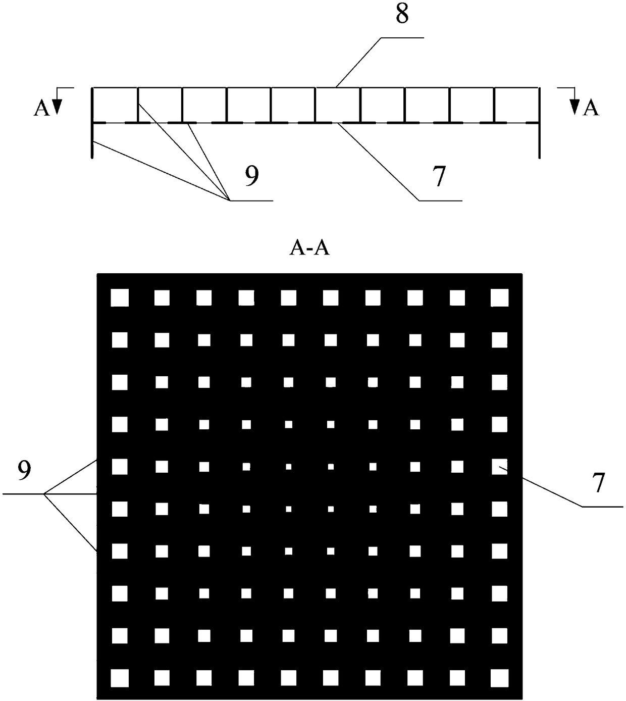
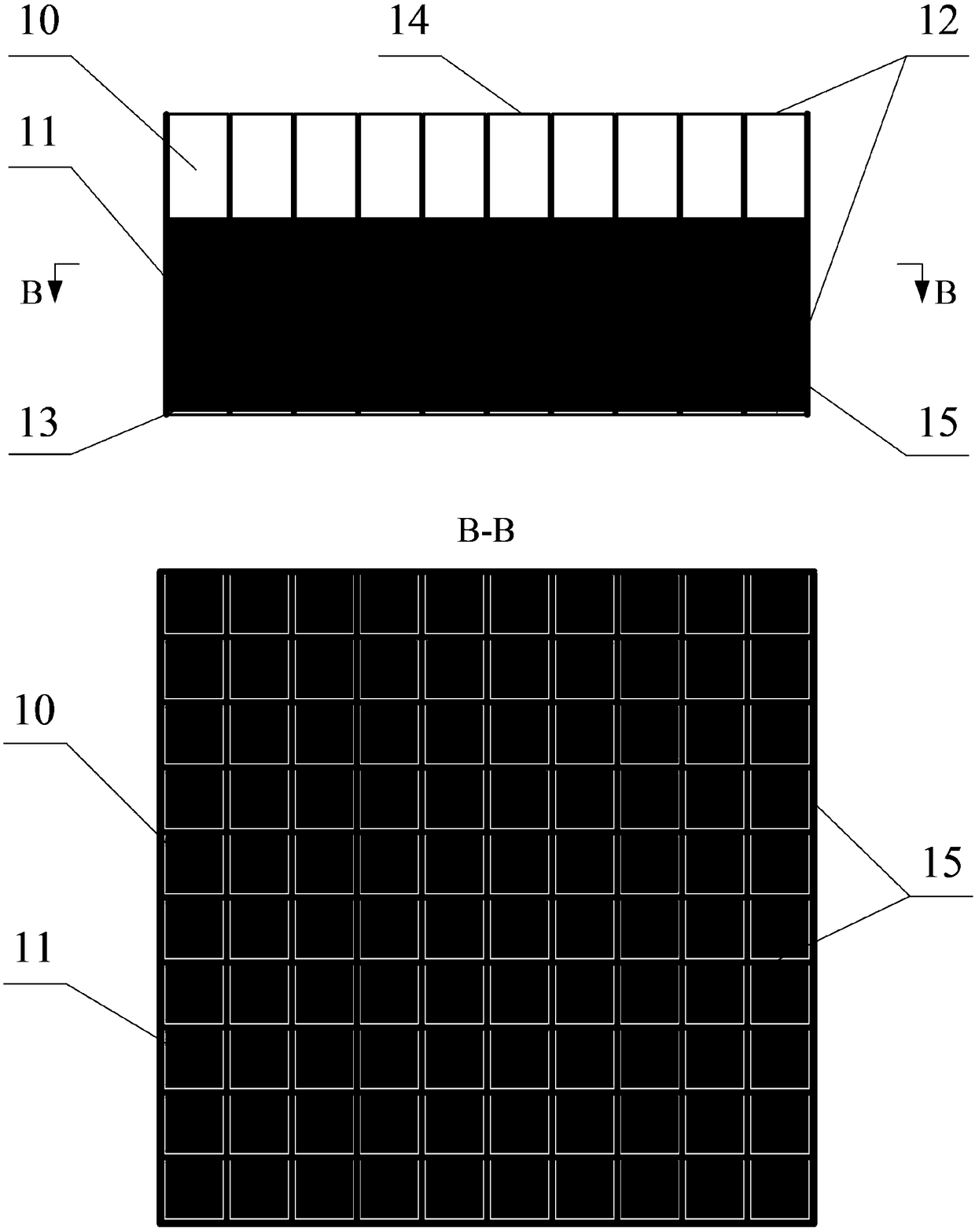
[0031] A fluidized bed cluster reactor, which is composed of an air inlet 1, an air outlet 2, a header 3, an air distribution plate 4, a fluidized bed cluster adsorption bed 5, and a shell 6; the cross section of the shell 6 is square; the inside of the header 3 Air inlet 7, air outlet 8 and manifold wall 9 are provided; the air outlet 8 of manifold 3 is square; the fluidized bed cluster adsorption bed 5 includes several bed pipes 10, granular materials 11 and leak-proof net 12 arranged side by side ; The bed tubes 10 in the fluidized bed cluster adsorption bed 5 are at the same height; the cross-sections of the bed tubes 10 are all square; the centers of the bed tubes 10 are arranged in parallel. The air inlet 1 of the reactor is connected to the header 3, and the header 3 is connected to the inlet 13 of the fluidized bed cluster adsorption bed 5, and the leak-proof net 12 prevents the granular material 11 in the bed pipe 10 from leaking out while ensuring the smooth flow of g...

Embodiment 2

[0033] A fluidized bed cluster reactor, which is composed of an air inlet 1, an air outlet 2, a header 3, an air distribution plate 4, a fluidized bed cluster adsorption bed 5, and a shell 6; the cross section of the shell 6 is square; the inside of the header 3 Air inlet 7, air outlet 8 and manifold wall 9 are provided; the air outlet 8 of manifold 3 is square; the fluidized bed cluster adsorption bed 5 includes several bed pipes 10, granular materials 11 and leak-proof net 12 arranged side by side ; The center of the bed tube 10 in the fluidized bed cluster adsorption bed 5 gradually rises as the distance from the center point of the reactor increases; the cross-sections of the bed tubes 10 are all square; the centers of the bed tubes 10 are arranged in parallel. The air inlet 1 of the reactor is connected to the header 3, and the header 3 is connected to the inlet 13 of the fluidized bed cluster adsorption bed 5, and the leak-proof net 12 prevents the granular material 11 in...

Embodiment 3

[0035] A fluidized bed cluster reactor, which is composed of an air inlet 1, an air outlet 2, a header 3, an air distribution plate 4, a fluidized bed cluster adsorption bed 5, and a shell 6; the cross section of the shell 6 is square; the inside of the header 3 An air inlet 7, an air outlet 8 and a manifold wall 9 are provided; the air outlet 8 of the manifold 3 is a regular hexagon; the fluidized bed cluster adsorption bed 5 includes several bed pipes 10 arranged side by side, granular materials 11 and anti-corrosion The leaking net 12; the bed tubes 10 in the fluidized bed cluster adsorption bed 5 are at the same height; the cross-sections of the bed tubes 10 are regular hexagons; the centers of the bed tubes 10 are arranged in parallel. The air inlet 1 of the reactor is connected to the header 3, and the header 3 is connected to the inlet 13 of the fluidized bed cluster adsorption bed 5, and the leak-proof net 12 prevents the granular material 11 in the bed pipe 10 from lea...


PUM


Abstract

The invention discloses a fluidized bed cluster reactor, and relates to the field of gas-solid reaction fluidization equipment. An air inlet, an air outlet and a header wall are arranged in a header,and the header wall divides the header into a long cavity communicated with the air inlet as well as a small cavity communicated with a plurality of fluidized bed cluster adsorption beds; the air inlet is formed in the small cavity and is communicated with the long cavity, and the fluidized bed cluster adsorption bed comprises a plurality of bed tubes arranged side by side, a granular material anda leak-proof net; the air outlet is formed in the small cavity and directly faces the inlet end of the bed tube, the gas to be treated flows into the long cavity of the header through the air inlet,passes through an air distributor through the air outlet of the header to flow into the bed tubes of the fluidized bed cluster adsorption bed, and then flows to the air outlet through the leak-proof net and then leaves the reactor. The fluidized bed cluster reactor disclosed by the invention has the beneficial effects that the problems of high pressure drop in the reactor and serious wear of the granular material are solved, the utilization rate of the granular material in the reactor is improved, and the replacement cost of the granular material is reduced, thereby achieving the purposes of high efficiency, energy saving and cost reducing.

Description

technical field [0001] The invention relates to the field of gas-solid reaction fluidization equipment, in particular to a fluidized bed cluster reactor. Background technique [0002] Gas-solid fluidized reactors are widely used in the fields of heterogeneous catalysis and gas separation due to their advantages such as small gas resistance, sufficient gas-solid contact, and good heat and mass transfer performance. The pressure drop of the reactor is an important factor determining the efficiency of the gas-solid reaction and the energy consumption of the reactor. It is directly proportional to the filling height of the granular materials (such as adsorbent particles, catalyst particles, etc.) in the reactor, reducing the filling height of the granular materials Although the pressure drop of the reactor is reduced, the scale of the reactor is reduced. The wear of the granular material in the reactor is an important factor determining the utilization rate of the granular mate...

Claims


Application Information

Patent Timeline
Patent Type & Authority Applications(China)
IPC IPC(8): B01D53/12B01J8/26
CPCB01D53/12B01J8/26
Inventor 李晓飞靳江涛祝方舟李庆党吕晓龙
Owner QINGDAO UNIV OF SCI & TECH
Learn More