Processing cooling device of numerical control center

A cooling device and cooling box technology, applied in metal processing equipment, metal processing machinery parts, manufacturing tools, etc., can solve the problems of poor cooling effect of coolant, reduced cooling effect of tools and parts, troublesome cleaning and maintenance, etc., to achieve Ensure the cooling effect, prolong the storage period, and prevent clogging

Active Publication Date: 2018-12-21
安庆市基丞精密机械有限公司
View PDF7 Cites 8 Cited by
  • Summary
  • Abstract
  • Description
  • Claims
  • Application Information

AI Technical Summary

Problems solved by technology

[0003] When the CNC center is working, the coolant is sprayed on the parts and tools to take away the heat, then flows into the bottom of the CNC center, and is re-sent to the surface of the parts and tools by the water pump, so that the coolant can be recycled. During the cooling process, the coolant absorbs The heat on the cutting tool and parts makes the temperature rise. The traditional heat dissipation device does not have a good cooling effect on the coolant, so that the coolant cannot discharge the heat in time, resulting in the temperature of the coolant gradually rising after the CNC center works for a long time. High, so that the cooling effect on the tool and parts is reduced. At the same time, when the water pump circulates the coolant, because the coolant is mixed with processing waste, the water pump is easy to cause blockage after long-term use, and it is troublesome to clean and maintain.

Method used


Image

  • Processing cooling device of numerical control center
  • Processing cooling device of numerical control center
  • Processing cooling device of numerical control center

Examples


Embodiment Construction

[0028] Through the description of the embodiments below, the specific implementation of the present invention includes the shape, structure, mutual position and connection relationship between the various parts, the function and working principle of each part, the manufacturing process and the operation and use method of the various components involved. etc., to make further detailed descriptions to help those skilled in the art have a more complete, accurate and in-depth understanding of the inventive concepts and technical solutions of the present invention. ", "Bottom", "Front", "Back", "Left", "Right", "Inner", "Outer", "Side", etc., are only for reference to the direction and position of the attached drawing, therefore, the used The terms of direction and position are used to illustrate and understand the present invention, but not to limit the present invention.

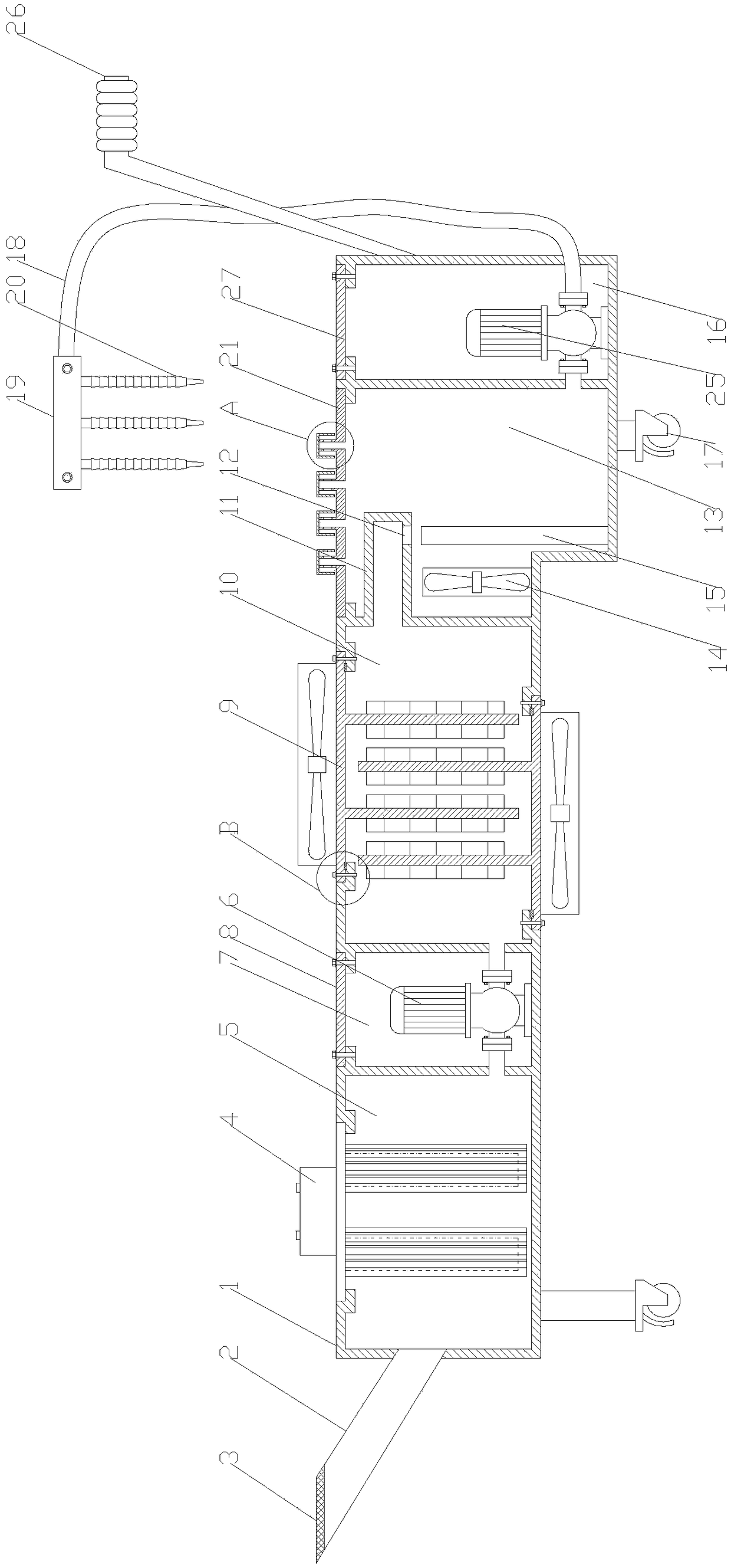
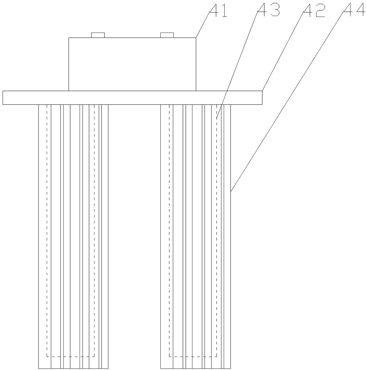
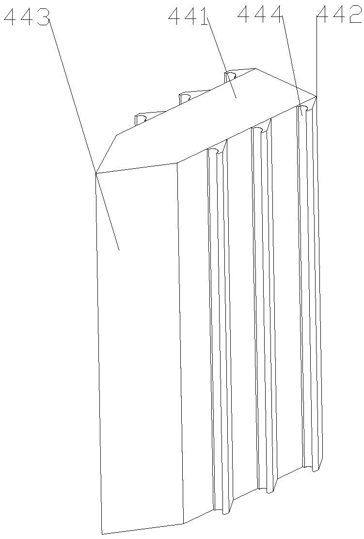
[0029] Such as Figure 1-8 As shown, the present invention is a machining cooling device of a numerical con...


PUM


Abstract

The invention discloses a processing cooling device of a numerical control center. The device comprises a cooling box; the cooling box is provided with an adsorption chamber, a placement chamber 1, acooling chamber 1, a cooling chamber 2 and a placement chamber 2 from left to right; the left side of the cooling box is provided with an inlet pipe communicating with the adsorption chamber; an adsorption device is arranged at the upper end of the adsorption chamber; a water pump 1 is arranged in the placement chamber; the water inlet end of the water pump 1 is connected with the adsorption chamber, and the water outlet end is connected with the cooling chamber 1; the upper end and the lower end of the cooling chamber 1 are provided with heat dissipating devices; the cooling chamber 1 communicates with the upper end of the cooling chamber 2; a water pump 2 is arranged in the placement chamber 2; the water inlet end of the water pump 2 is communicates with the lower end of the cooling chamber 2; the water outlet end of the water pump 2 is provided with a connecting tube; the front end of the connecting pipe is provided with a water pipe seat; and the lower end of the water pipe seat isprovided with a plurality of universal pipes. The device recovers the cooling liquid when working in the numerical control center, separates the processing waste in the cooling liquid, and cools thecooling liquid, so that a coolant can be recycled and maintains a good cooling effect.

Description

technical field [0001] The invention belongs to the technical field of numerical control centers, and in particular relates to a processing cooling device for numerical control centers. Background technique [0002] When the CNC center is performing machining, the friction between the high-speed rotating tool and the part will generate a lot of heat, which will cause the surface temperature of the part and the tool to rise rapidly. Spray coolant. Coolant is an industrial liquid used to cool and lubricate cutting tools and workpieces. The coolant is scientifically formulated with a variety of super functional additives. Rust performance, degreasing and cleaning performance, anti-corrosion function, no adverse effects on the CNC center itself, it has good cooling, cleaning, anti-rust and other characteristics. [0003] When the CNC center is working, the coolant is sprayed on the parts and tools to take away the heat, then flows into the bottom of the CNC center, and is re-se...

Claims


Application Information

Patent Timeline
Patent Type & Authority Applications(China)
IPC IPC(8): B23Q11/10
CPCB23Q11/10B23Q11/1069
Inventor 孙涛赵峰王子彬张玲牛敬仁潘克福
Owner 安庆市基丞精密机械有限公司
Why Eureka
Try Eureka