
Swing system and swing control method for aerial work platform

An aerial work platform and controller technology, which is applied to fluid pressure actuating devices, servo motors, lifting devices, etc., can solve problems such as high cost of proportional valves, difficulty in accurately controlling the moving position of the gondola, and great influence of speed control. , to achieve the effect of improving energy saving, controllability and fretting

Active Publication Date: 2019-12-03
徐州兆恒工控科技有限公司
View PDF2 Cites 0 Cited by
  • Summary
  • Abstract
  • Description
  • Claims
  • Application Information

AI Technical Summary

Problems solved by technology

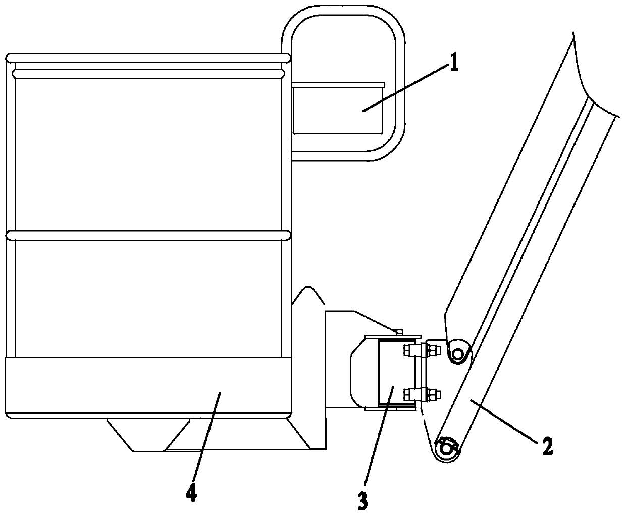
When swinging close to the boom 2 or the installed items when working at high altitude, the fretting of the swing movement of the hanging basket 4 is poor, which makes it difficult to accurately control the movement position of the hanging basket
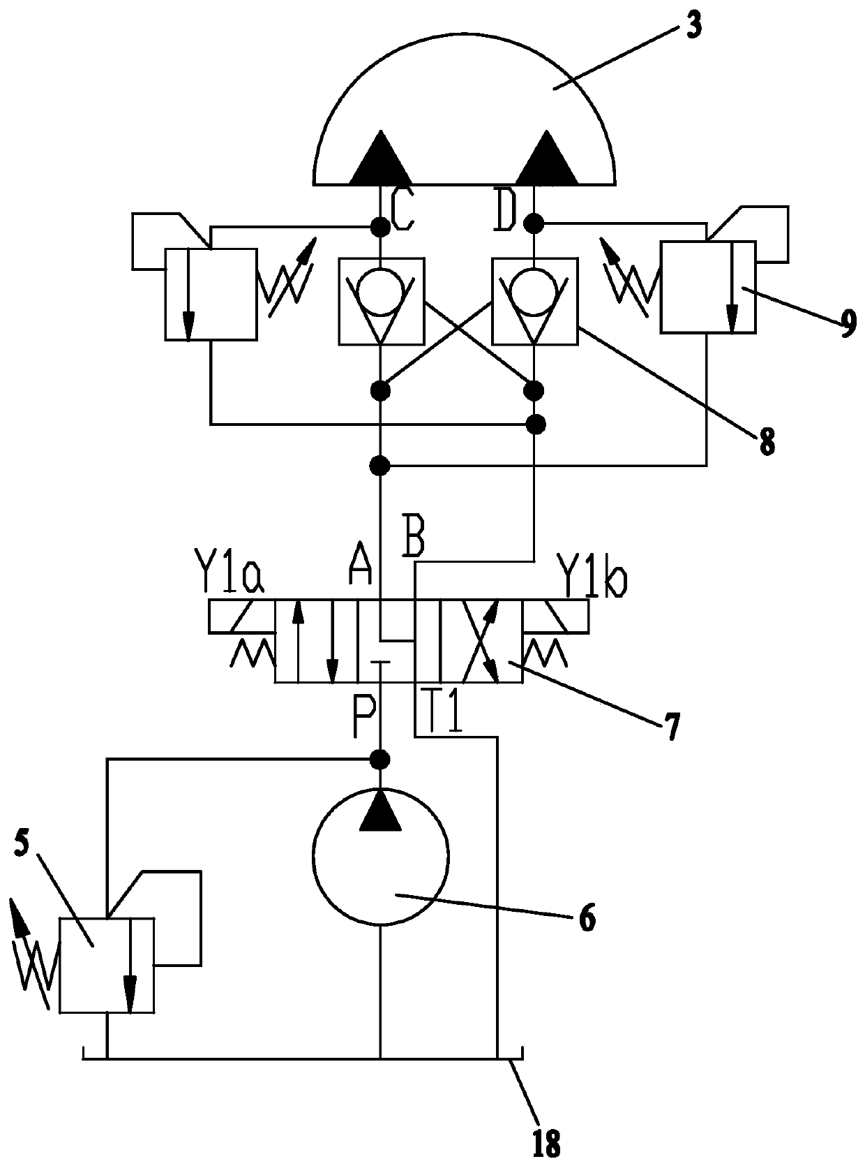
[0007] When the swing cylinder 3 is in motion, the flow required by the hydraulic system is relatively small, generally 0.7L / min~2L / min. If the first three-position four-way reversing valve 7 is changed from the switch value control to the proportional control, there will be the following Two big problems: one is the high cost of proportional valves with small flow rates; the other is that the leakage increases when the oil temperature rises, and there may be no swinging action when the handle is at a small angle, which has a great impact on the speed control
[0008] Quantitative pump 6 is used for oil supply, and quantitative pump 6 can provide more oil, except for the oil required by the system, other oil overflows back to the oil tank, and the energy saving performance is poor

Method used


Image

  • Swing system and swing control method for aerial work platform
  • Swing system and swing control method for aerial work platform
  • Swing system and swing control method for aerial work platform

Examples


Embodiment Construction

[0036] The present invention will be further described below in conjunction with specific drawings and embodiments.

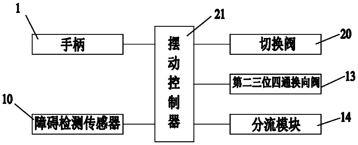
[0037] Such as image 3 and Figure 4 As shown: in order to effectively control the swing speed of the hanging basket 4 according to the angle of the handle, the present invention includes a hanging basket 4, a swing cylinder 3 for driving the hanging basket 4 to swing, and a handle for manipulating the swinging state of the hanging basket 4 1; It also includes a hydraulic swing control circuit for driving and controlling the work of the swing cylinder 3 and a swing controller 21 electrically connected to the handle 1;

[0038] The hydraulic swing control circuit includes a constant pressure variable pump 11, a second three-position four-way reversing valve 13 for controlling the reversing of the swing cylinder 3, and a regulator for stabilizing the flow through the second three-position four-way reversing valve 13. The speed valve 12 and the balance valve va...


PUM


Abstract

The invention relates to a platform swing system and a swing control method, and particularly relates to an aerial work platform swinging system and a swing control method. The invention belongs to the technical field of aerial work platforms. A swing controller obtains the position state of a handle, the swing controller can control the working state of a switching valve, a second three-positionfour-way reversing valve, and the shunt module according to the position state of the handle, so that the speed of the swing oil cylinder driving the hanging basket is matched with the current position state of the handle, namely, different flow rates can be provided to the swing cylinder according to the position state of the handle, so that the speed of the swing oil cylinder driving swing basket can be hierarchically and discretely controlled, and the controllability and the micro-motion are high, safe and reliable. When the handle is in a neutral state, the constant-pressure variable pumpworks in a pressure cut-off state, and the output flow is almost zero,; when the handle is in the non-neutral state, the constant-pressure variable pump works in the constant pressure variable state,the flow rate is automatically adjusted according to the system demand, thereby improving the energy saving performance of the swing system.

Description

technical field [0001] The invention relates to a platform swing system and a swing control method, in particular to an aerial work platform swing system and a swing control method, belonging to the technical field of aerial work platforms. Background technique [0002] The aerial work platform is a special wheeled vehicle designed for urban infrastructure construction and maintenance. System, hydraulic system, electrical system and other parts. Operators perform high-altitude operations on the hanging basket, and the rated load capacity of the hanging basket is generally 220Kg or 340Kg. [0003] In order to improve the operation convenience of the aerial work platform, the aerial work platform needs to be rotated at high altitude. It is common practice now that, by operating the handle 1, the hanging basket 4 of the aerial work platform can almost swing around 180° through the swing cylinder 3. The hanging basket 4 and the jib 2 are connected by a swing cylinder 3, such ...

Claims


Application Information

Patent Timeline
Patent Type & Authority Patents(China)
IPC IPC(8): B66F11/00B66F9/075B66F9/22F15B11/08F15B13/04
CPCB66F9/0755B66F9/22B66F11/00F15B11/08F15B13/022F15B13/04F15B2211/20546
Inventor 臧其亮史俊青付红贺建华徐志鹏国芳崔洁
Owner 徐州兆恒工控科技有限公司
Learn More