
Industrial kiln for ceramic material production

A ceramic material and industrial technology, used in furnaces, charge materials, box furnaces, etc., can solve the problems of failure to integrate combustion and cooling, and simplify processing, and achieve functional diversification, reduce processing costs, and reduce labor. Effect

Inactive Publication Date: 2018-12-21
SUZHOU LUOTELAN NEW MATERIAL TECH
View PDF5 Cites 2 Cited by
  • Summary
  • Abstract
  • Description
  • Claims
  • Application Information

AI Technical Summary

Problems solved by technology

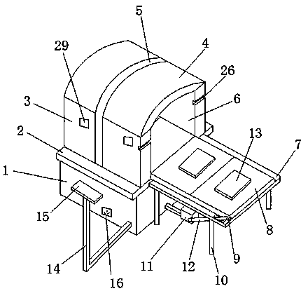
[0002] A kiln is a device made of refractory materials for firing products. It is an essential facility in pottery molding. Human beings have a history of tens of thousands of years of ceramic firing, and have accumulated a wealth of kiln-making styles and experience. From open-air pile firing on the ground, digging pits and firing to steamed bun-shaped rising-flame circular kilns, half-down-flame horseshoe-shaped kilns, banpo dragon kilns, duck-egg-shaped kilns, and now indoor gas kilns and electric kilns, kiln technology is constantly improving and developing. Among them, the traditional kiln firing ceramics can only achieve combustion and shaping, and the processing is simplified, and the combustion and cooling are not integrated. Therefore, an industrial kiln for the production of ceramic materials is provided.

Method used


Image

  • Industrial kiln for ceramic material production
  • Industrial kiln for ceramic material production
  • Industrial kiln for ceramic material production

Examples


Embodiment Construction

[0021] The preferred embodiments of the present invention will be described below in conjunction with the accompanying drawings. It should be understood that the preferred embodiments described here are only used to illustrate and explain the present invention, and are not intended to limit the present invention.

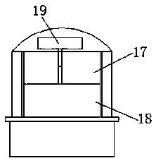
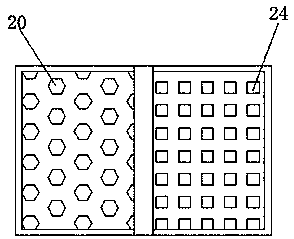
[0022] like Figure 1-Figure 7 As shown, an industrial kiln for the production of ceramic materials includes a base 1, and the top of the base 1 is provided with an operation table 2, and the operation table 2 includes a cooling furnace 3, a high-temperature furnace 4, and an isolation device 5. The cooling furnace 3 is connected with the high-temperature furnace 4 through the isolation device 5. By setting the cooling furnace 3 and the high-temperature furnace 4, the firing, shaping and cooling of ceramic materials can be integrated, which reduces working time and improves work efficiency. One end of the furnace 4 is provided with a kiln mouth 6, and one end of the...


PUM


Abstract

The invention relates to an industrial kiln for ceramic material production. The industrial kiln comprises a base; a console is arranged at the top of the base; the console comprises a cooling furnace, a high-temperature furnace and an isolation device; the cooling furnace is connected with the high-temperature furnace through the isolation device; a kiln port is formed in one end of the high-temperature furnace; a conveying table is arranged at one end of the console; a conveying belt is arranged at the top of the conveying table; belt wheels are arranged on two sides of the conveying belt; support columns are arranged at the bottom of the conveying table; a motor is arranged at the bottom of the conveying table; linkage belts are arranged between the motor and the belt wheels; the motoris connected with the belt wheels through the linkage belts; a ceramic placing plate is arranged above the conveying belt; a control table is arranged on one side of the base; a switch controller is arranged at the top of the control table; and a power supply socket is arranged on one side of the bottom of the base. The industrial kiln reduces the environment pollution, reduces the machining cost,and achieves various functions and high practicability.

Description

technical field [0001] The invention relates to an industrial kiln used for the production of ceramic materials, belonging to the field of kiln technical equipment. Background technique [0002] A kiln is a device made of refractory materials for firing products. It is an essential facility in pottery molding. Human beings have a history of tens of thousands of years of ceramic firing, and have accumulated a wealth of kiln-making styles and experience. From open-air pile firing on the ground, digging pits and firing to steamed bun-shaped rising-flame circular kilns, half-down-flame horseshoe-shaped kilns, banpo dragon kilns, duck-egg-shaped kilns, and now indoor gas kilns and electric kilns, kiln technology is constantly improving and developing. Among them, the traditional kiln firing ceramics can only achieve combustion and shaping, and the processing is simplistic, and there is no integration of combustion and cooling. Therefore, an industrial kiln for the production of c...

Claims


Application Information

Patent Timeline
IPC IPC(8): F27B17/00F27D3/12F27D15/02F27D19/00
CPCF27B17/0041F27B17/0075F27B2017/0091F27D3/12F27D15/0266F27D19/00F27D2003/121F27M2001/035
Inventor 马志明
Owner SUZHOU LUOTELAN NEW MATERIAL TECH
Learn More