
Modeling firework with novel handheld electric ignition rotating structure

A new type of electric ignition technology, applied in pyrotechnics, weapon types, offensive equipment, etc., can solve the problems of inconvenient and unsafe discharge, achieve the effect of increasing packaging and storage capacity, convenient operation and use, and beautiful appearance

Inactive Publication Date: 2018-12-21
浏阳市普迹镇金旺烟花鞭炮厂
View PDF0 Cites 1 Cited by
  • Summary
  • Abstract
  • Description
  • Claims
  • Application Information

AI Technical Summary

Problems solved by technology

[0002] At present, hand-held rotating fireworks are generally ignited and set off manually. The rotating body is a single tube structure, and the hand-held parts are bamboo sticks or wooden poles or thin iron rods. When the drug burns, it produces flames and the reaction force of gas jets to form a moment of rotation around the axis to make the jetted colored flames or sparks form a ring shape, which is generally called "one-character fire wheel" fireworks. "Wheel" fireworks are only suitable for outdoor display; in the prior art, the luminescent rotating firework used for indoor display, the small ones are rotated around hanging wires or hung with iron nails, the large ones are rotated by wheels with bushings, and the small ones are rotated Fireworks are ignited by artificial ignition, and large fireworks are ignited by electric ignition. Especially when small-scale fireworks are set off on indoor stages, hand-held rotating fireworks still use manual ignition, which is extremely inconvenient and unsafe to set off. At present, there is no live fire on the market. Modeling fireworks with hand-held electric ignition and self-rotating structure with the structure of the head ignition device and the structure of the piezoelectric ceramic ignition device

Method used


Image

  • Modeling firework with novel handheld electric ignition rotating structure
  • Modeling firework with novel handheld electric ignition rotating structure

Examples


Embodiment Construction

[0016] In order to further illustrate the above-mentioned purpose, structural features and effects of the present invention, the present invention will be further described in detail below in conjunction with the accompanying drawings and embodiments:

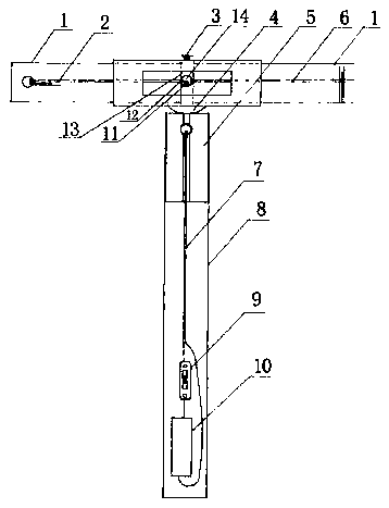
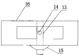
[0017] figure 1 , figure 2 A preferred embodiment of the invention is shown. Its composition: consists of rotating body 1, fire transmission lead 2, central axis 3, igniter 4, fire transmission device 5, wire 7, rotating parts 8, switch 9, battery box 10 and so on. Among them, the rotating body 1 is a paper effect cylinder or a plastic effect cylinder equipped with various sprays, spraying micro-smoke or smokeless medicine, and the end of the effect cylinder can be processed and set as a single-hole spray eye according to the discharge requirements and needs. Or multi-hole combined injection eye; igniter 4 is molded into an umbrella shape with plastic once; fire transmission device 5 is processed with wood or metal material,...


PUM


Abstract

The invention discloses a modeling firework with a novel handheld electric ignition rotating structure. The modeling firework is characterized by comprising a rotating body, a fire transfer fuse, an igniter, a fire transfer device and a rotating part; the igniter is integrated by an effect cylinder sleeve, a shaft sleeve and a tray, wherein the upper part of the shaft sleeve is perpendicular to aninner cavity in the center position of a center shaft of the effect cylinder sleeve; the effect cylinder sleeve is spaced into left and right cylinder sleeves, and the lower end extends to the external position of the lower bottom surface of the tray through the center of the tray connected to the outer wall of the cylinder sleeve under the effect cylinder sleeve; the fire transfer hole is formedin the front middle position of the shaft sleeve at the upper part of the tray; the effect cylinder sleeve is transversely provided with a long opening corresponding to the fire transfer hole in thefront middle position of the shaft sleeve; and the rotating body is a rotating body with a combined structure by a split effect cylinder with multiple spraying holes at two ends and left and right effect cylinder sleeves on the igniter.

Description

technical field [0001] The invention belongs to the technical field of pyrotechnics, and in particular relates to a novel hand-held electrically ignited and self-rotating shaped firework suitable for indoor or outdoor hand-held discharge, which can change the shape effect and is environmentally safe. Background technique [0002] At present, hand-held rotating fireworks are generally ignited and set off manually. The rotating body is a single tube structure, and the hand-held parts are bamboo sticks or wooden poles or thin iron rods. When the drug burns, it produces flames and the reaction force of gas jets to form a moment of rotation around the axis to make the jetted colored flames or sparks form a ring shape, which is generally called "one-character fire wheel" fireworks. "Wheel" fireworks are only suitable for outdoor display; in the prior art, the luminescent rotating firework used for indoor display, the small ones are rotated around hanging wires or hung with iron na...

Claims


Application Information

Patent Timeline
Patent Type & Authority Applications(China)
IPC IPC(8): F42B4/00
CPCF42B4/00
Inventor 汤良兴李友刘玉红
Owner 浏阳市普迹镇金旺烟花鞭炮厂
Learn More