Wireless laser matrix monitoring system and method for deformation observation of surface area
A wireless laser and monitoring system technology, which is applied in the direction of using optical devices, measuring devices, instruments, etc., can solve the problems that the ground deformation in mining subsidence areas cannot be continuously observed, and achieve the effect of avoiding installation difficulties and highlighting technical advantages
- Summary
- Abstract
- Description
- Claims
- Application Information
AI Technical Summary
Problems solved by technology
Method used
Image
Examples
Embodiment 1
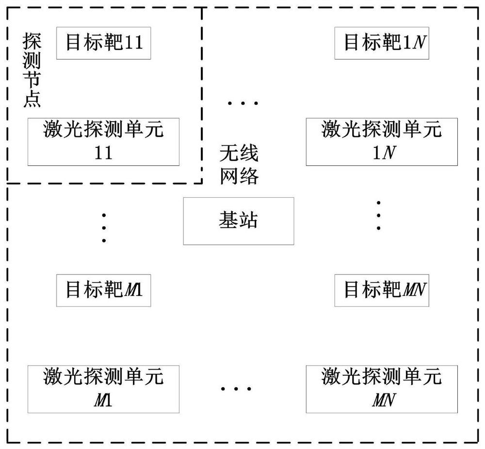
[0063] A specific embodiment of the present invention discloses a wireless laser matrix monitoring system for deformation observation of the surface area, such as figure 1 As shown, the wireless laser matrix monitoring system includes an M×N field displacement detection array composed of M×N laser detection units, a base station, and the like. Wherein, the quantities of M and N are determined according to the size of the area to be monitored and the layout requirements. Two-way data transmission is performed between the field displacement detection array and the base station through a wireless network.
[0064] The on-site displacement detection array is arranged in the surface area to be monitored, and the layout method can be uniformly arranged to monitor possible mining subsidence, landslides, cracks and other surface deformations in the surface area to be monitored.
[0065] Each laser detection unit is equipped with a corresponding independent target, and the target is s...
Embodiment 2
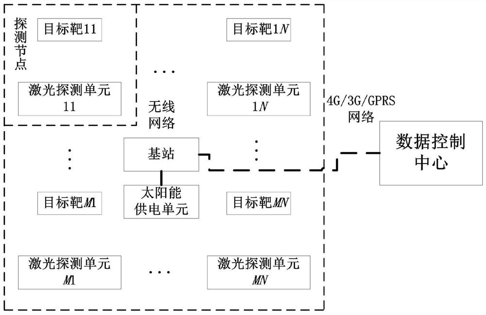
[0072] Optimizing on the basis of Embodiment 1, the wireless laser matrix monitoring system for surface area deformation observation also includes a solar power supply unit, a data control center, such as figure 2 shown.
[0073] The output terminal of the solar power supply unit is connected with the power supply terminal of the base station to provide power for the operation of the base station. The on-site displacement detection array is equipped with a replaceable power supply, which is replaced regularly by professional and technical personnel, and does not use a solar power supply unit for power supply.
[0074] The data control center further analyzes and displays the processing results of all base stations in different surface areas to be monitored, which helps to find the location where the deformation of the surface area first begins or is the most serious. The data control center includes a computer and supports 4G / 3G / GPRS communication. Correspondingly, the remot...
Embodiment 3
[0095] A specific embodiment of the present invention discloses a method of using the wireless laser matrix monitoring system described in Embodiment 2 to observe the deformation of the surface area, such as Figure 8 shown, including the following steps:
[0096] S1. On-site displacement detection arrays are arranged in the surface area to be monitored. The distance between each laser detection unit should be less than 500m, and the deformation position between the laser detection unit and the target spans the surface area, and there is no obstacle between the two; wireless data transmission The vertical height between the first antenna of the module and the ground is not less than 1m. The total number of detection nodes can be arranged according to the horizontal and vertical coordinates is 2 to 126.
[0097] S2. Arrange the base station in the surface area to be monitored. The distance between the base station and each laser detection unit should be less than 1km. The vert...
PUM
 Abstract
Description
Claims
Application Information
 - R&D
- Intellectual Property
- Life Sciences
- Materials
- Tech Scout
- Unparalleled Data Quality
- Higher Quality Content
- 60% Fewer Hallucinations
Browse by: Latest US Patents, China's latest patents, Technical Efficacy Thesaurus, Application Domain, Technology Topic, Popular Technical Reports.
© 2025 PatSnap. All rights reserved.Legal|Privacy policy|Modern Slavery Act Transparency Statement|Sitemap|About US| Contact US: help@patsnap.com


