
Method and device for detecting surface topography of fixed abrasive grinding tool

A technology of consolidating abrasives and surface topography, applied in the direction of measuring devices, optical devices, instruments, etc., can solve the problems of diffraction, sensitivity to environmental factors, and inability to accurately reflect the actual topography of the abrasive tool surface, and achieve high cost effects

Active Publication Date: 2018-12-21
TIANJIN UNIV
View PDF11 Cites 6 Cited by
  • Summary
  • Abstract
  • Description
  • Claims
  • Application Information

AI Technical Summary

Problems solved by technology

However, non-contact measurement, especially the optical measurement method is very sensitive to environmental factors, and the grains of different shapes are randomly distributed on the surface of the abrasive tool, which is easy to cause diffraction
Holes or deep grooves formed on the surface during the manufacturing or dressing process of abrasive tools will cause light scattering, making the corresponding areas imaged as bright spots (black holes), which are difficult to be identified, resulting in the detection results of the abrasive tool surface cannot accurately reflect the abrasive tool surface Actual landform
At present, there is no mature measuring device in the market that can comprehensively and accurately detect the surface topography of bonded abrasives such as grinding wheels and abrasive belts, and then evaluate their grinding performance.

Method used


Image

  • Method and device for detecting surface topography of fixed abrasive grinding tool
  • Method and device for detecting surface topography of fixed abrasive grinding tool
  • Method and device for detecting surface topography of fixed abrasive grinding tool

Examples


Embodiment Construction

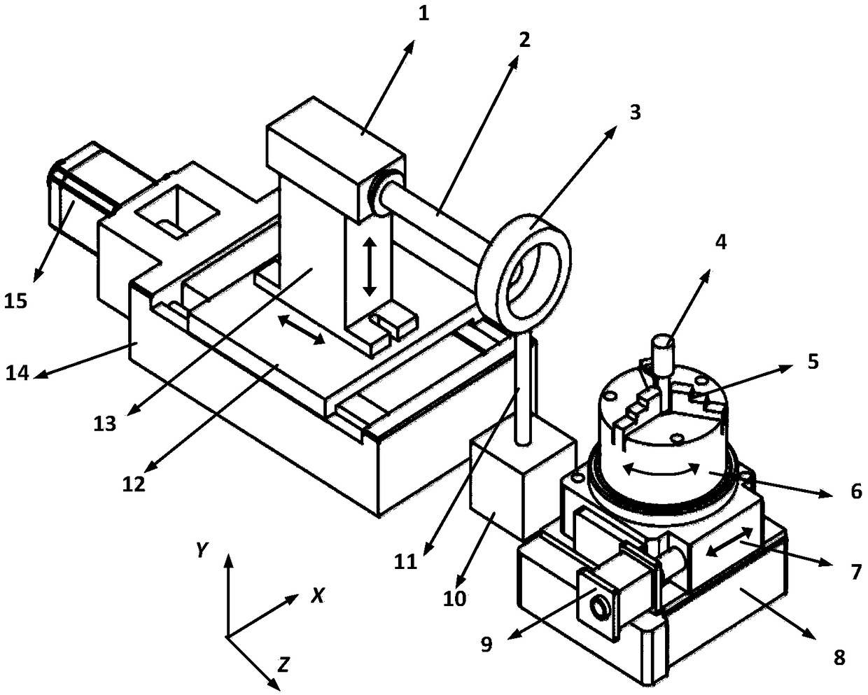
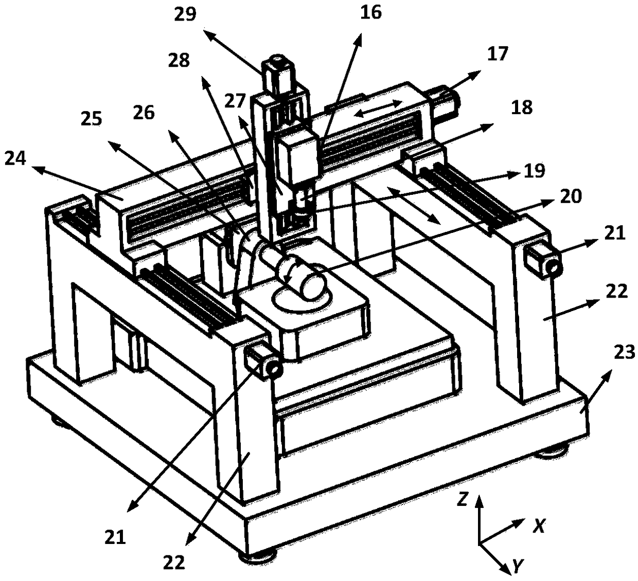
[0038] The specific implementation manners of the present invention will be described in detail below in conjunction with the accompanying drawings.

[0039] The surface topography detection method of the consolidated abrasive tool of the present invention comprises the following steps:

[0040] Step 1. Connect the CCD camera to the computer through the image acquisition card. The CCD camera transmits the screen of the measured bonded abrasive to the computer and displays it on the computer monitor. Change the position of the CCD camera and rotate the measured bonded abrasive so that The CCD camera lens is aimed at the measured surface area of ​​the measured fixed abrasive abrasive;

[0041] Step 2: When using the CCD camera to obtain the topography information of the surface of the measured bonded abrasive tool, since a single image can only obtain two-dimensional information of the measured area, it is impossible to directly obtain the complete three-dimensional information ...


PUM


Abstract

The invention discloses a method and device for detecting the surface topography of a fixed abrasive grinding tool. The method comprises the following steps that a CCD camera is connected to a computer through an image acquisition card, the CCD camera transmits the image of the fixed abrasive grinding tool to be detected to the computer and displays the image on a computer monitor, and the position of the CCD camera is changed and the fixed abrasive grinding tool to be detected is rotated so that a lens of the CCD camera can be aligned with a detected surface area of the fixed abrasive grinding tool to be detected; surface topography images of the detected area of the grinding tool are acquired continuously to form an image sequence, and the acquired surface topography images of the detected area of the fixed abrasive grinding tool to be detected are transmitted to the computer form image processing; and the acquired three-dimensional information of the surface topography of the fixedabrasive grinding tool is used for calculating the surface three-dimensional evaluation parameters in accordance with the international standard ISO25178-2, and the evaluation of the surface topography of the fixed abrasive grinding tool is realized. The method and device do not cause abrasion and damage to the grinding tool.

Description

technical field [0001] The invention relates to a method and a device for detecting the surface topography of a workpiece, in particular to a method and a device for detecting the surface topography of a consolidated abrasive tool. Background technique [0002] Hard and brittle materials are widely used in aerospace, biomedical, electronic communications, automobiles, new energy and other industrial fields. At present, precision ultra-precision grinding using bonded abrasive tools is still the most effective method for hard and brittle materials. Consolidated abrasives have strong material removal ability, low wear rate, long service life, stable grinding process, easy to obtain high surface quality and processing efficiency, etc. The abrasive grains whose surface protrudes from the bond perform micro-cutting on the surface of the workpiece to achieve precise and ultra-precision surface processing. Therefore, the microscopic topography of the abrasive tool surface, such as...

Claims


Application Information

Patent Timeline
Patent Type & Authority Applications(China)
IPC IPC(8): G01B11/30
CPCG01B11/303
Inventor 仇中军汤骏杰李天一
Owner TIANJIN UNIV
Learn More