
Throat pressure tapping nozzle and device using same

A throat and nozzle technology is applied in the field of throat pressure taking nozzles and devices using the nozzles, which can solve the problems of high processing difficulty, influence on flow measurement, influence on flow field, etc. Qualification rate, ensure the effect of coaxiality

Pending Publication Date: 2018-12-21
KAIFENG INSTR
View PDF0 Cites 0 Cited by
  • Summary
  • Abstract
  • Description
  • Claims
  • Application Information

AI Technical Summary

Problems solved by technology

Disadvantages of this structure: 1. The front and rear straight pipe sections are an integral structure, which cannot be realized in technology; 2. If the front and rear straight pipe sections have a two-section structure, it will inevitably cause the pressure-taking pipe to pass through the weld seam. For high-pressure and high-temperature media 3. The throttling part adopts the integrated structure of the nozzle and the throat, and the rear expansion section and the throat adopt a welded structure. Defects such as bosses, depressions, and dislocations are prone to occur at the connection parts. It has an impact on the flow field and reduces the uncertainty of flow measurement; 5. The pass rate of factory inspection is low
Disadvantages of this structure: 1. It is difficult to ensure the coaxiality of the nozzle axis and the front straight pipe section; 2. The nozzle throat pressure hole adopts a 4-section broken line design, which is complex in process, difficult in processing, high in cost, and prone to burrs and misalignment and other defects, which are not easy to detect and seriously affect the flow measurement; 3. The nozzle adopts a three-stage structure, and the accuracy is not easy to improve
Disadvantages of this structure: 1. It is difficult to ensure the coaxiality of the nozzle axis and the front straight pipe section; 2. The nozzle throat pressure hole adopts a 4-section broken line design, which is complex in process, difficult in processing, high in cost, and prone to burrs and misalignment and other defects, and it is not easy to check and find, which seriously affects the flow measurement; 3. The inspection pass rate is low; currently there are also methods such as Image 6 The nozzle structure shown, but also has the above disadvantages, but the processing is slightly easier

Method used


Image

  • Throat pressure tapping nozzle and device using same
  • Throat pressure tapping nozzle and device using same
  • Throat pressure tapping nozzle and device using same

Examples


Embodiment Construction

[0035] The technical solution of the present invention will be further described in detail in conjunction with the following drawings.

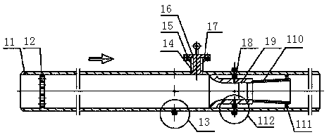
[0036] like Figure 7 As shown, a throat pressure-taking nozzle is used as a standard measuring instrument for measuring the flow rate of a steam turbine in a power plant, including a nozzle 81, a throat 82 and a rear expansion section 83, and the nozzle 81, the throat 82 and the rear expansion section 83 are integral structures; The throat 81 is provided with a pressure-taking hole 84, which is perpendicular to the axis of the nozzle 81, and the throat pressure-taking hole 84 is a straight hole for pressure-taking.

[0037] Further, a cylindrical surface is provided at the front of the nozzle 81, and the cylindrical surface is used as a positioning cylindrical surface.

[0038]Further, a support ring 85 is provided on the rear expansion section 83 .

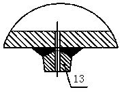
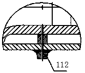
[0039] like Figure 8 , Figure 9 , Figure 10 As shown, a device using a throat press...


PUM


Abstract

The invention provides a throat pressure tapping nozzle and a device using the same. The throat pressure tapping nozzle is characterized in that a nozzle body, the throat and a rear expanding sectionare of an overall structure; and the throat is provided with a pressure tapping hole, and the pressure tapping hole of the throat is perpendicular to the axis of the nozzle body and conducts straighthole pressure tapping. The throat pressure tapping nozzle is applied to the measuring device for measuring the water flow of a steam turbine, machining can be facilitated, the structure and the technology are simplified, using reliability and safety are improved, the verifying pass percent is increased, and the measuring precision is improved.

Description

technical field [0001] The invention relates to the field of measuring instruments, in particular to a throat pressure-taking nozzle and a device using the nozzle. Background technique [0002] In modern large-scale thermal power generation systems, it is necessary to calculate the heat consumption rate and steam consumption rate of the steam turbine. To calculate the heat consumption rate and steam consumption rate of the steam turbine, it is necessary to accurately know the flow rate entering the steam turbine. Low β value throat pressure ASME PTC6 The .0 nozzle is a standard flow meter for measuring the water flow entering the steam turbine. The ASME PTC6.0 nozzle with low β value throat pressure can be used as the benchmark for flow value transmission and is an important equipment for steam turbine verification. [0003] According to the installation position, the flowmeter of the power plant to measure the water entering the steam turbine is divided into: the downstream...

Claims


Application Information

Patent Timeline
Patent Type & Authority Applications(China)
IPC IPC(8): G01F1/42
CPCG01F1/42
Inventor 郭铁军张金艳张建勇林洋房相如靳文哲吴志军林峰李金聚沈磊王波付宁超刘长礼李晓芳张红琴高玉香李国选王刚
Owner KAIFENG INSTR
Learn More