
A dry etching apparatus

A technology of dry etching and equipment, which is applied in the manufacture of discharge tubes, electrical components, semiconductors/solid-state devices, etc. It can solve the problems of different etching rates, affecting the quality of wafers, and uneven etching of wafer edge areas. , to achieve the effect of improving quality, uniform distribution, and improving etching uniformity

Inactive Publication Date: 2018-12-21
HUAIAN IMAGING DEVICE MFGR CORP
View PDF5 Cites 7 Cited by
  • Summary
  • Abstract
  • Description
  • Claims
  • Application Information

AI Technical Summary

Problems solved by technology

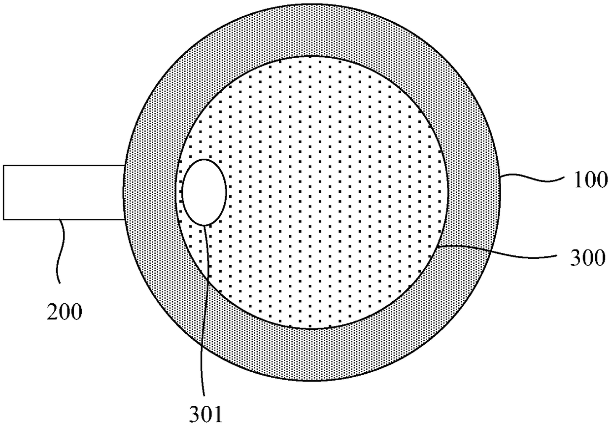
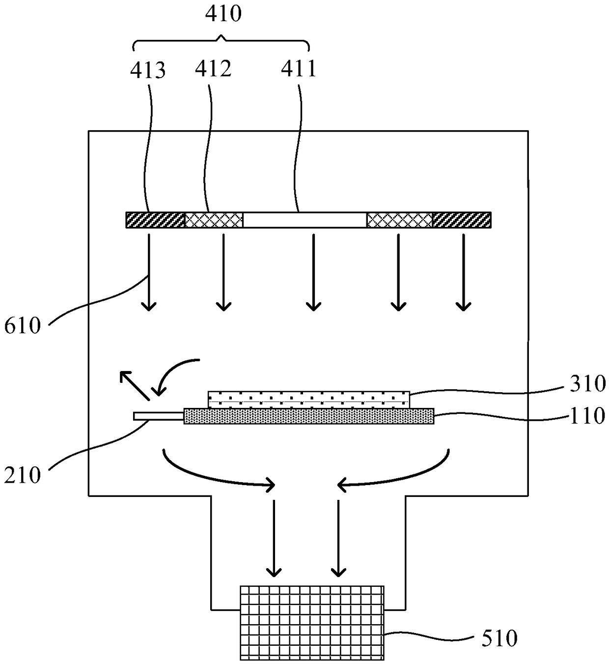
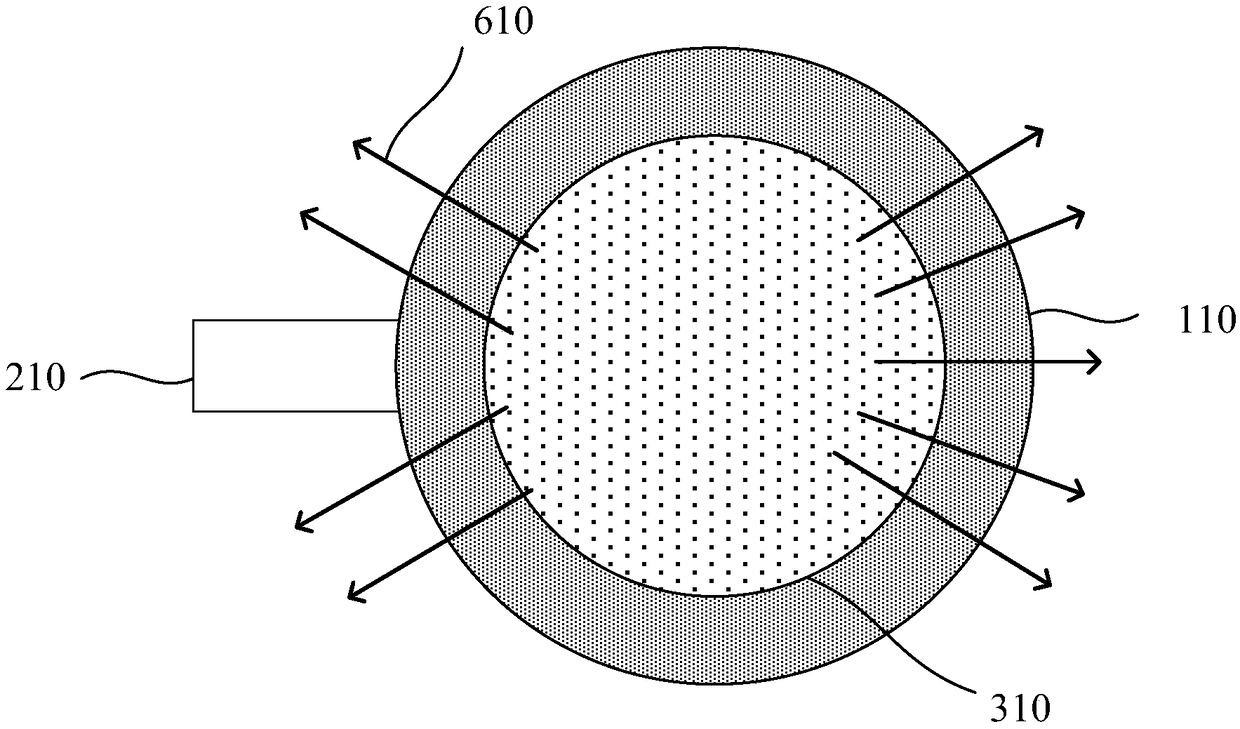
[0007] In view of the above-mentioned shortcomings of the prior art, the purpose of the present invention is to provide a dry etching device for solving the problem that the prior art can only roughly regulate the distribution of the reaction gas, but cannot precisely adjust the distribution of the reaction gas. And in the existing Lam machine, due to the protruding cantilever contained under the ESC, the reactive gas distribution in the edge area of ​​the wafer is uneven when the gas is pumped, resulting in different etching rates in the edge area of ​​the wafer. The etching of the edge area is uneven, which affects the quality of the subsequent wafer preparation

Method used


Image

  • A dry etching apparatus
  • A dry etching apparatus
  • A dry etching apparatus

Examples


Embodiment Construction

[0039] The implementation of the present invention will be illustrated by specific specific examples below, and those skilled in the art can easily understand other advantages and effects of the present invention from the contents disclosed in this specification.

[0040] see Figure 2 to Figure 4 . It should be noted that the structures, proportions, sizes, etc. shown in the drawings attached to this specification are only used to match the content disclosed in the specification, for those who are familiar with this technology to understand and read, and are not used to limit the implementation of the present invention. Limiting conditions, so there is no technical substantive meaning, any modification of structure, change of proportional relationship or adjustment of size, without affecting the effect and purpose of the present invention, should still fall within the scope of the present invention. The disclosed technical content must be within the scope covered. At the sa...


PUM


Abstract

A dry etching apparatus includes a gas supply portion located in an upper electrode of the dry etching apparatus and disposed parallel to a wafer, a lower surface area of the gas supply portion beingnot smaller than an upper surface area of the wafer,. The gas supply portion sequentially comprises a central region, an intermediate region surrounding the central region and an edge region surrounding the intermediate region from inside to outside, wherein the edge region is divided into at least two edge region gas chambers, and the edge region gas chambers penetrate the edge region; The waferhas a uniform etching rate by adjusting the reaction gas in each region of the gas supply portion.

Description

technical field [0001] The invention belongs to the field of semiconductor equipment and relates to dry etching equipment. Background technique [0002] Etching is a technology that removes materials using chemical reactions or physical impacts. In fact, in a narrow sense, it is photolithographic etching. Etching treatment to remove the part that needs to be removed. Generally, etching technology can be divided into wet etching and dry etching. It is a very important process in semiconductor manufacturing process, microelectronics manufacturing process and micro-nano manufacturing process. The step is the main process of patterning (pattern) processing associated with photolithography. [0003] Plasma etching is the most common form of dry etching. Its principle is: the gas exposed to the electronic region forms a plasma. When the plasma is accelerated by an electric field, it will release enough energy to promote the plasma and material The surface reacts. At present, i...

Claims


Application Information

Patent Timeline
Patent Type & Authority Applications(China)
IPC IPC(8): H01J37/32H01L21/67
CPCH01J37/32449H01J2237/3343H01L21/67069
Inventor 罗林盖晨光陈杰刘家桦叶日铨
Owner HUAIAN IMAGING DEVICE MFGR CORP
Learn More