Device for detecting outer cutter swing of CNC cutter machine

A technology of detection device and external knife, applied in mechanical measuring device, measuring device, using mechanical device, etc., can solve the problems of easy wear and exchange, inconvenient exchange, lower machine startup rate, larger diameter data, etc., to achieve convenient Regular cleaning, reducing the requirements for cleaning and cleanliness, and the effect of simple structure

Pending Publication Date: 2018-12-25
KUNSHAN XUZHENG PRECISION MACHINERY
View PDF0 Cites 5 Cited by
  • Summary
  • Abstract
  • Description
  • Claims
  • Application Information

AI Technical Summary

Problems solved by technology

[0002] Tool pendulum refers to the deviation between the running diameter of the tool and the standard diameter of the tool due to various reasons caused by the machine tool spindle or the tool when the tool is moving. The common way to measure the tool pendulum is to use the calibration point on the diameter of the rotating tool The difference between the readings is the number of swings. To put it simply, the shape of the tool rotates outward, and the diameter data becomes larger. Measuring the tool swing is to know the real running diameter of the tool, so as to prevent the tool from making the workpiece smaller. As long as you know the tool swing number, you can The program can be modified, or the tool clamping can be adjusted to achieve accurate processing according to the workpiece data. However, the existing CNC tool machine external tool swing detection device detects after the spindle rotates after the tool is hung on the CNC machine. This tool swing detection The defect of the method is that the detection of knife pendulum takes up the running time of the machine, which delays the efficiency of the machine and reduces the operating rate of the machine, thereby reducing the output value of the machine. Some knife pendulum detection equipment, when the cone surface of this type of equipment contacts , the equipment is in contact with the cone surface of the tool handle, and the inside of the equipment can be rotated. When the cone surface is a little dirty, the surface contact will easily affect its accuracy. In addition, the cone surface is easy to wear and interchangeable when it is used for a long time, and it is inconvenient to replace this equipment. The high price is also a big investment for ordinary small businesses, which cannot meet the current people's requirements for this product

Method used


Image

  • Device for detecting outer cutter swing of CNC cutter machine
  • Device for detecting outer cutter swing of CNC cutter machine
  • Device for detecting outer cutter swing of CNC cutter machine

Examples


Embodiment Construction

[0017] The present invention will be further described below in conjunction with specific embodiments, wherein, the accompanying drawings are only for exemplary illustrations, and what are shown are only schematic diagrams, rather than actual pictures, and should not be understood as limitations to this patent, based on the specific embodiments of the present invention All other specific implementation methods obtained by persons of ordinary skill in the art without creative efforts fall within the protection scope of the present invention.

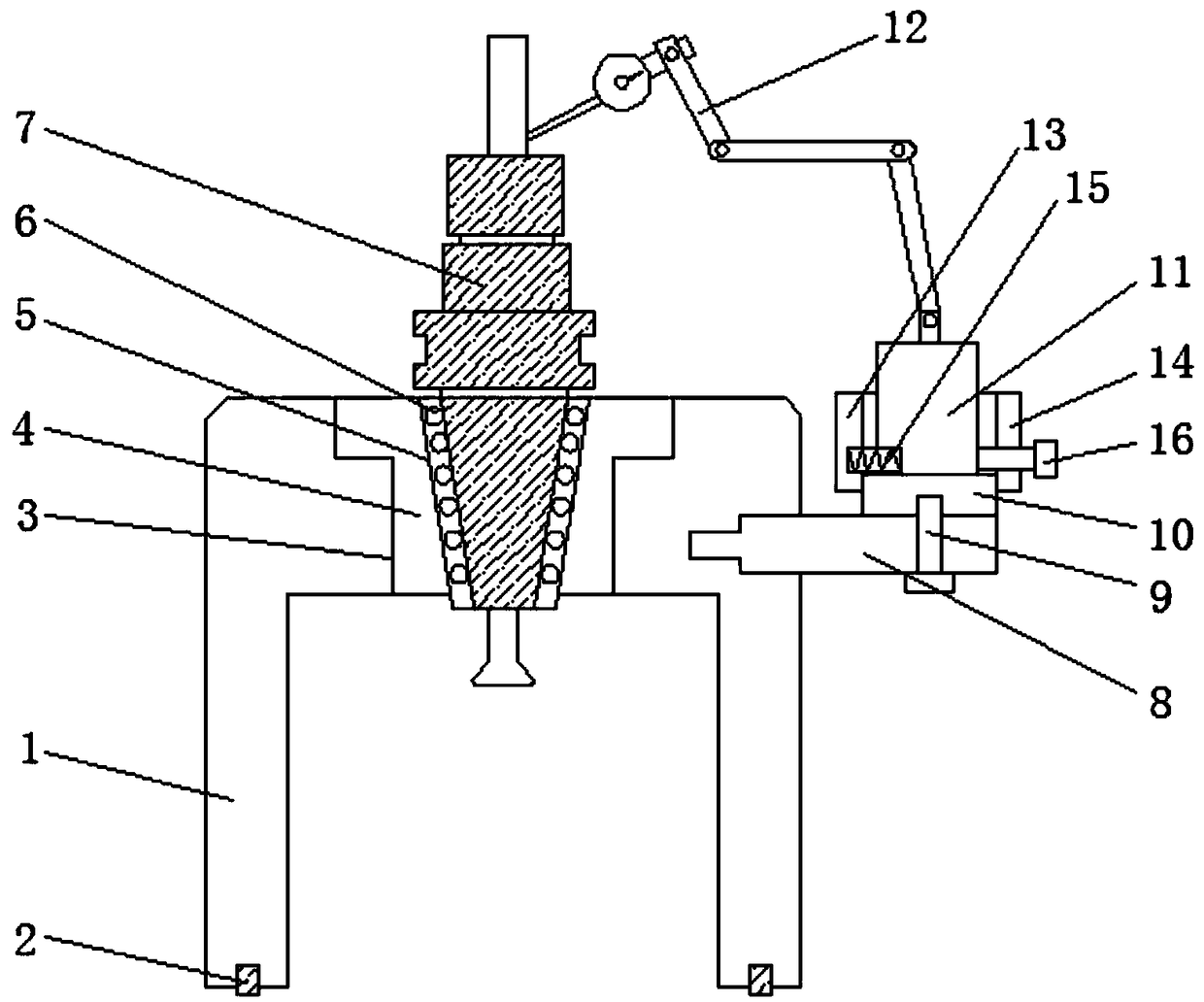
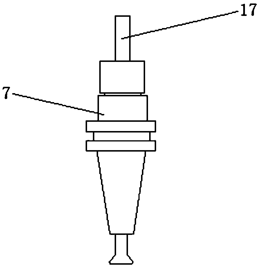
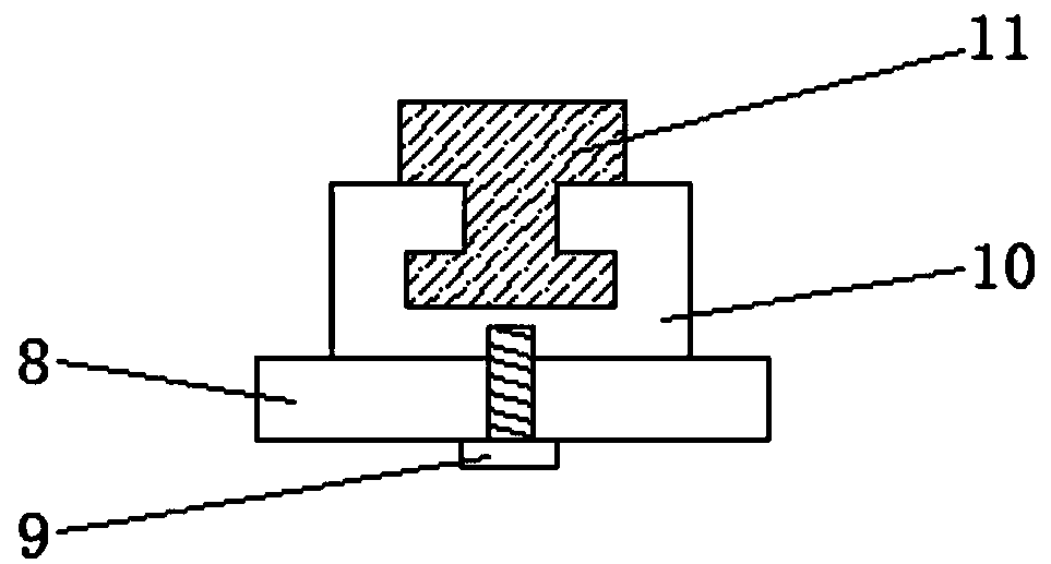
[0018] see Figure 1-Figure 3 , the present invention provides a technical solution: a CNC cutting tool machine external knife swing detection device, including a base 1, an annular sealing ring 2 is embedded in the bottom of the base 1, and an installation groove 3 is opened in the center of the top of the base 1, The installation groove 3 is embedded with a taper block 4, which can stably fix the taper block 4. A bushing 5 is set inside...


PUM


Abstract

The invention discloses a device for detecting outer cutter swings of a CNC cutter machine, which comprises a base. An annular sealing ring is embedded in the bottom of the base; a mounting groove isarranged through the center of the top of the base; a taper block is embedded in the mounting groove; the inner side of the taper block is sleeved with a bushing; steel balls are evenly distributed inthe inner side of the bushing; the inner side of the bushing is rotationally sleeved with a knife handle system; and a supporting block is embedded in one side of the top of the base. The device fordetecting outer cutter swings of a CNC cutter machine is simple in structure and convenient to manufacture. Multi-point contact is adopted to reduce a contact area between the knife handle and equipment, and reduce the requirement of a clean degree during use, which is convenient for quick use; a detachable steel ball bushing is adopted, the bushing is convenient for regular cleaning, and a worn bushing can be directly replaced, so that the interchangeability is strong; it is convenient to adjust the position of a scale when bouncing the cutter swing, and the position of the scale can be automatically reset; and the structure of the device is made of aluminum, the rubber sealing ring is anti-slip, the device is convenient to move, easy to carry, and has wide application prospects.

Description

technical field [0001] The invention relates to the technical field of mechanical processing practical tools, in particular to a detection device for the outer cutter swing of a CNC cutter machine. Background technique [0002] Tool pendulum refers to the deviation between the running diameter of the tool and the standard diameter of the tool due to various reasons caused by the machine tool spindle or the tool when the tool is moving. The common way to measure the tool pendulum is to use the calibration point on the diameter of the rotating tool The difference between the readings is the number of swings. To put it simply, the shape of the tool rotates outward, and the diameter data becomes larger. Measuring the tool swing is to know the real running diameter of the tool, so as to prevent the tool from making the workpiece smaller. As long as you know the tool swing number, you can The program can be modified, or the tool clamping can be adjusted to achieve accurate process...

Claims


Application Information

Patent Timeline
Patent Type & Authority Applications(China)
IPC IPC(8): G01B5/00G01M13/00
CPCG01B5/00G01M13/00
Inventor 刘伟革童海林
Owner KUNSHAN XUZHENG PRECISION MACHINERY
Why Eureka
Try Eureka