Lifting filter structure

A filter structure, lifting technology, applied in the field of daily necessities, can solve the problems of difficulty in realizing the tea-brewing function, cumbersomeness, inability to realize the tea-water separation function, etc., and achieve the effects of simple shape, improved space utilization, and reduced volume

Pending Publication Date: 2018-12-28
厦门意树创意设计有限公司
View PDF16 Cites 1 Cited by
  • Summary
  • Abstract
  • Description
  • Claims
  • Application Information

AI Technical Summary

Problems solved by technology

[0004] The above-mentioned detachable and washable structure of the tea cup is covered with an outer cup to form a tea cup. It is commonly known as an "elegant cup" in the tea cup industry. The main function of the detachable and washable inner cup is to soak and filter tea: put the tea leaves Pour an appropriate amount of boiling water into the inner cup, and after the tea leaves have soaked for a suitable time, open the piston, and the tea will flow into the outer cup to form isolation from the tea leaves in the inner cup. The detachable and washable structure of the tea making cup is reliable, but there are Disadvantages, the premise of this scheme to achieve tea separation is that there is a water level difference between the inner cup leak hole and the outer cup, and the tea in the inner cup is discharged into the outer cup to achieve the function of tea separation. The outer cup must be made relatively higher and larger. It is relatively bulky, otherwise, when the water level of the outer cup is equal to that of the inner cup, the tea in the inner cup cannot leak into the outer cup, and the tea separation function cannot be realized. Small, when the tea in the outer cup is at the same level as the water in the inner cup, it is difficult for the tea in the outer cup to form effective convection with the tea in the inner cup, and it is difficult to realize the popular tea making function

Method used


Image

  • Lifting filter structure
  • Lifting filter structure
  • Lifting filter structure

Examples


Embodiment 1

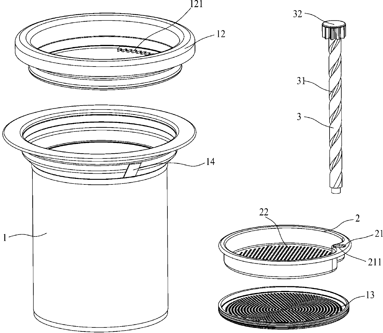
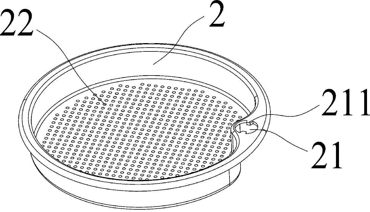
[0025] Such as Figure 2 to Figure 4 As shown, a lifting filter structure described in this embodiment includes a receiving part 1, a movable frame 2 and a guide post 3; the receiving part 1 is a hollow cylindrical structure, and the receiving part 1 is provided with a guide post The fixed hole 11, the guide post 3 is assembled in the receiving part 1 and rotatably inserted in the guide post fixing hole 11, and the surface is provided with a spiral guide groove 31, and the movable frame 2 is movably assembled in the receiving part 1 Inside, the movable frame 2 is provided with a guide post hole 21 that matches the guide post 3 and is movably sleeved on the guide post 3, and the guide post hole 21 is provided with a bump 211 that matches the guide post spiral guide groove 31 , so that the movable frame 2 can reciprocate in the receiving part 1 with the rotation of the guide post 3 .

[0026] There are at least two guide post fixing holes 11 , which are located at the upper end...

Embodiment 2

[0035] A lifting filter structure of the present invention is the same as embodiment 1 except the following technical features, as Figure 5 As shown, the outer side of the receiving part 1 is provided with a card platform 15, which is similar to the elastic part in embodiment 1, so that the receiving part can be detachably fixed on the outer cup (not shown in the figure).


PUM


Abstract

The invention discloses a lifting filter structure, which comprises a container part, a movable frame and a guide pillar, wherein the container part refers to a hollow cylindrical structure provided with guide pillar fixing holes, the guide pillar is assembled in the container part and particularly is rotationally inserted in the fixing holes, and is provided with a helical guide slot on the surface, the movable frame is movably assembled in the container part and provided with a guide pillar hole matched with the guide pillar and movably sleeving the guide pillar, and the guide pillar hole isprovided with a lug matched with the helical guide slot of the guide pillar so that the movable frame can reciprocate in the container part along with rotation of the guide pillar. The lifting filterstructure is simple in structure, reliable in action and wide in application range; a tea making machine utilizing the filter structure is small in size and much convenient to carry with as comparedwith the conventional tea makers.

Description

technical field [0001] The invention relates to the field of daily necessities, in particular to a lifting filter structure. Background technique [0002] Drinking tea is the living habit of most people, and teacups are the most used for making tea. [0003] A Chinese patent discloses a detachable and washable tea cup structure (authorized announcement number CN 207574973 U), and the technical solution described in claim 1 is (see also figure 1 ): "A detachable and washable tea cup structure, including a cup body 1', an opening 12' is provided in the center of the bottom of the cup body 1', a filter screen 13' is provided above the opening, and the filter screen 13' is connected to the opening There is a water gap 14' reserved between the holes 12', which is characterized in that it also includes a fixing seat 2', a fixing ring 3' and a water control assembly 4', and the filter screen 13' is fixed on the fixing seat 2 through the filter screen frame 15' ', the fixed seat 2...

Claims


Application Information

Patent Timeline
Patent Type & Authority Applications(China)
IPC IPC(8): A47G19/22
CPCA47G19/2211
Inventor 洪文国
Owner 厦门意树创意设计有限公司
Why Eureka
Try Eureka