Mass concrete circulating cooling system

A circulating cooling system and mass concrete technology, applied in the field of concrete pouring, can solve the problems of not considering temperature distribution, concrete damage, low boundary temperature, etc., so as to prevent and limit crack propagation, prevent concrete cracks, and reduce temperature stress Effect

Inactive Publication Date: 2018-12-28
SHANXI CONSTR ENG CO LTD
View PDF8 Cites 7 Cited by
  • Summary
  • Abstract
  • Description
  • Claims
  • Application Information

AI Technical Summary

Problems solved by technology

The current arrangement of cold water pipes is mostly uniform, without considering the temperature distribution inside the actual concrete block. Although it can control the temperature drop inside the concrete and reduce the temperature difference between the inside and outside of the concrete, due to the difference in heat dissipation effect, the temperature in the center of the concrete is high, and the boundary The temperature is low, and the arrangement of equal-spaced water pipes cannot effectively reduce the internal temperature difference of the concrete. This internal temperature difference will still generate unfavorable temperature stress and have great destructive power to the concrete.

Method used


Image

  • Mass concrete circulating cooling system

Examples


Embodiment 1

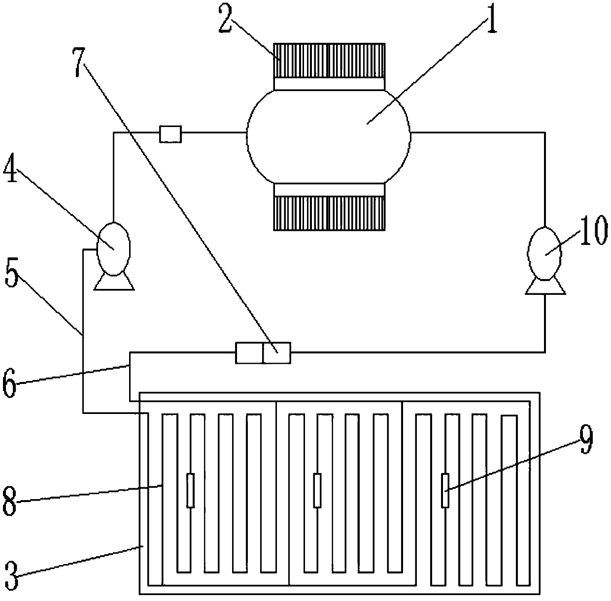
[0020] Such as figure 1 As shown, the large-volume concrete circulating cooling system includes a water storage tank 1, a cooling device 2 and a plurality of cooling water networks 3. The water storage tank 1 is connected to the water inlet end of the water inlet pump 4 through a pipeline, and the drain end of the water inlet pump 4 is connected to the water supply pipeline. 5 connected, the water inlet of each cooling water network 3 is connected with the water supply pipe 5, and the outlet of each cooling water network 3 is connected with the return water pipe 6, and the return water pipe 6 is equipped with a flow limiting valve 7, and the return water pipe 6 It communicates with the water inlet end of the return water pump 10, and the discharge end of the return water pump 10 communicates with the water storage tank 1 through a pipeline. The cooling water in the storage tank 1 is sent into the cooling water network 3 through the water inlet pump 4, and the cooling water net...

Embodiment 2

[0030] Compared with Embodiment 1, this embodiment differs in the temperature and flow rate of the cooling water in the water supply pipe, specifically: the temperature difference between the water temperature in the water supply pipe 5 and the pouring concrete is controlled within 15°C, and the cooling water in the cooling water network 3 The flow rate is controlled at 1m / s, the time from entering the cooling water network 3 to leaving the cooling water network 3 is controlled at 150s, and the difference between the water temperature at the water inlet of the cooling water network 3 and the water temperature at the outlet of the cooling water network 3 Controlled at 3°C. By controlling the temperature and flow rate of the water in the cooling water network 3, the cooling effect of the cooling water network 3 on the poured concrete can be adjusted to avoid cracking of the concrete and ensure the quality of the concrete after solidification.

Embodiment 3

[0032]Compared with Embodiment 1, this embodiment differs in the temperature and flow rate of the cooling water in the water supply pipe, specifically: the temperature difference between the water temperature in the water supply pipe 5 and the pouring concrete is controlled within 20°C, and the cooling water in the cooling water network 3 The flow velocity is controlled at 0.85m / s, the time from entering the cooling water network 3 to leaving the cooling water network 3 is controlled at 180s, and the difference between the water temperature at the water inlet of the cooling water network 3 and the water temperature at the outlet of the cooling water network 3 The value is controlled at 5°C. By controlling the temperature and flow velocity of the water in the cooling water network 3, the cooling effect of the cooling water network 3 on poured concrete can be adjusted to avoid cracking of the concrete and ensure the quality of the concrete after solidification.


PUM


Abstract

The invention belongs to the technical field of concrete pouring, and particularly relates to a mass concrete circulating cooling system. According to the technical scheme, the mass concrete circulating cooling system comprises a water storing tank and a plurality of cooling water screens. The water storing tank communicates with a water inlet end of a water inlet pump by a pipeline. The water outlet end of the water inlet pump communicates with a water supplying pipeline. Water inlets of the cooling water screens communicate with the water supplying pipeline. Water outlets of the cooling water screens communicate with a backwater pipeline. The backwater pipeline is provided with a flow limiting valve. The backwater pipeline communicates with the water inlet end of a backwater pump. The water outlet end of the backwater pump communicates with the water storing tank by a pipeline. Cooling water in the water storing tank is conveyed to the water inlet pump to the cooling water screens. The cooling water screens are positioned in raft foundation concrete, can stably cool the poured concrete, and can conduct effective heat dissipation to concrete in the hydration process. The cooling water absorbs mass heat in the cooling water screens and is conveyed back to the water storing tank by the backwater pump, and therefore circulating application is achieved.

Description

technical field [0001] The invention belongs to the technical field of concrete pouring, and in particular relates to a circulation cooling system applied to large-volume concrete pouring. Background technique [0002] In the construction industry, large-volume concrete structures are often encountered, such as dam bodies, power station water intake towers, pier foundations, building foundations, etc. During the construction period of large-volume concrete, concrete hydration will generate a lot of heat. If it cannot be effectively Uniform heat dissipation will form a large temperature stress, resulting in concrete cracking and quality accidents. In order to prevent cracks caused by the large temperature difference between the inside and outside of the concrete, cooling water pipes are embedded in the concrete, and temperature control measures such as cooling and watering the concrete are taken to ensure the quality of the concrete. The current arrangement of cold water pip...

Claims


Application Information

Patent Timeline
IPC IPC(8): E02D15/02C04B40/02
CPCC04B40/02E02D15/02
Inventor 翟桂庆王瑞兵宋立国李喜涛陈义红姚建新
Owner SHANXI CONSTR ENG CO LTD
Why Eureka
Try Eureka