Automatic identification device and method of optical fiber fusion splicer

An optical fiber fusion splicer and automatic identification technology, applied in the directions of light guides, optics, optical components, etc., can solve the problems of difficulty in distinguishing optical fibers, restricting motion accuracy, and difficult to keep up, avoiding mis-splicing, improving the quality of optical fiber fusion, and adjusting fast effect

Active Publication Date: 2018-12-28
南京迪威普光电技术股份有限公司
View PDF4 Cites 1 Cited by
  • Summary
  • Abstract
  • Description
  • Claims
  • Application Information

AI Technical Summary

Problems solved by technology

[0003] The design concept of the core alignment device is to form an effective precision drive in a limited space to align the end faces of the optical fibers on the two core alignment frames on the same axis, such as the three-dimensional automatic alignment core alignment device of the optical fiber fusion splicer disclosed in CN201373927Y. The cross-alignment method uses the cam and the slider to drive the two aligning frames to move in the cross direction respectively. However, the movement accuracy of the device is restricted by the cam shape and the processing capacity of the guide groove, and it is difficult to keep up with the increasing Increased alignment accuracy is required when
[0004] At present, most of the cameras on the fusion splicer are fixed-focus lenses, but in actual operation, different types of optical fibers are difficult to distinguish with the naked eye alone, and it is easy to mistakenly connect different types of optical fibers. A fiber identification method is proposed for the optical fiber fusion splicer Require

Method used


Image

  • Automatic identification device and method of optical fiber fusion splicer
  • Automatic identification device and method of optical fiber fusion splicer
  • Automatic identification device and method of optical fiber fusion splicer

Examples


Embodiment

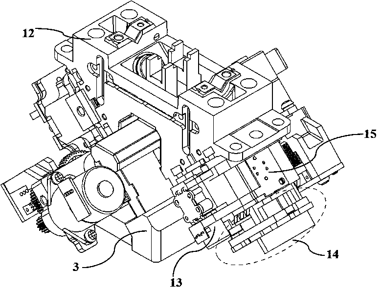
[0029] The automatic identification device of the optical fiber fusion splicer in this embodiment is as follows: figure 1 As shown, automatic focusing is realized by an automatic focusing motor 13 , a camera assembly 14 and an automatic focusing lens assembly 15 installed on a central mounting bracket 12 . There are 45° slopes on both sides of the center mounting bracket 12 for installing the auto-focusing lens assembly 15 , the slopes on both sides are symmetrical to each other, and the center mounting bracket 12 is fixedly connected to the centering frame base 3 .

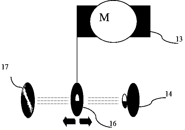
[0030] The principle of automatic focus adjustment is as follows: figure 2 As shown, the autofocus motor 13 drives the adjusting lens 16 to move linearly, and the focal length of the lens assembly formed with the fixed lens 17 changes, and automatically adapts when the position and type of the optical fiber change, ensuring the imaging accuracy of the camera assembly 14. The imaging accuracy meets the needs of ...


PUM


Abstract

The invention provides an automatic identification device and method of an optical fiber fusion splicer. The device comprises a core adjusting frame component and a power component, which are installed on a base, and two groups of optical fiber identification components installed on both sides of a central mounting bracket, wherein the central mounting bracket is fixedly connected with the base; the core adjusting frame component is composed of a pair of centrally symmetric elastic supporting sheet and core adjusting frame, which are integrally connected with the base; and the power componentis a lead screw mechanism driven by a motor and a gear mechanism, which is used for pushing the core adjusting frame. The method comprises: identifying and learning various kinds of different opticalfibers, identifying and storing feature values of different optical fibers by using an image processing program, and identifying the optical fibers by matching the feature values. The automatic identification device provided by the invention has a compact structure and a high adjustment speed, realizes automatic focusing and identification of the optical fibers, and completely avoids mis-fusion ofdifferent types of optical fibers.

Description

technical field [0001] The invention relates to a device for connecting optical fibers through fusion, in particular to an automatic identification device and method for an optical fiber fusion splicing machine. Background technique [0002] The quality of optical fiber fusion is generally judged by the fusion loss and the strength of the fusion point. Among them, the size of the splice loss is more critical. Improving and improving the fiber-to-core level is the main way to reduce splicing loss and improve splicing quality. During fiber splicing, the alignment of the fiber core is very important, and the alignment accuracy of the alignment device directly affects the alignment level. [0003] The design concept of the core alignment device is to form an effective precision drive in a limited space to align the end faces of the optical fibers on the two core alignment frames on the same axis, such as the three-dimensional automatic alignment core alignment device of the op...

Claims


Application Information

Patent Timeline
Patent Type & Authority Applications(China)
IPC IPC(8): G02B6/255
CPCG02B6/2553G02B6/2555
Inventor 潘泳
Owner 南京迪威普光电技术股份有限公司
Why Eureka
Try Eureka