
An indoor photoelectric integrated optical fiber composite low-voltage power cable distribution box

A technology of optical fiber composite and low-voltage power, which is applied in the substation/power distribution device shell, electrical components, substation/switch layout details, etc., can solve the problems of cumbersome installation of power cables and reduced service life, etc., to reduce confusion and reduce Effect of heat loss, ease of maintenance or repair

Inactive Publication Date: 2018-12-28
合肥先杰新能源科技有限公司
View PDF6 Cites 2 Cited by
  • Summary
  • Abstract
  • Description
  • Claims
  • Application Information

AI Technical Summary

Problems solved by technology

[0004] The purpose of the present invention is to provide an indoor optoelectronic integrated optical fiber composite low-voltage power cable distribution box to solve the problem that the traditional indoor optoelectronic integrated optical fiber composite low voltage power cable distribution box is installed indoors. Installed with the wall, the rear wall of the indoor photoelectric integrated optical fiber composite low-voltage power cable distribution box is directly in contact with the wall, which makes the installation of the power cable more cumbersome, and the indoor photoelectric integrated optical fiber will also be damaged due to the corrosion of the wall. The problem of reduced service life of composite low-voltage power cable distribution box

Method used


Image

  • An indoor photoelectric integrated optical fiber composite low-voltage power cable distribution box
  • An indoor photoelectric integrated optical fiber composite low-voltage power cable distribution box
  • An indoor photoelectric integrated optical fiber composite low-voltage power cable distribution box

Examples


Embodiment Construction

[0026] The following will clearly and completely describe the technical solutions in the embodiments of the present invention with reference to the accompanying drawings in the embodiments of the present invention. Obviously, the described embodiments are only some, not all, embodiments of the present invention. Based on the embodiments of the present invention, all other embodiments obtained by persons of ordinary skill in the art without creative efforts fall within the protection scope of the present invention.

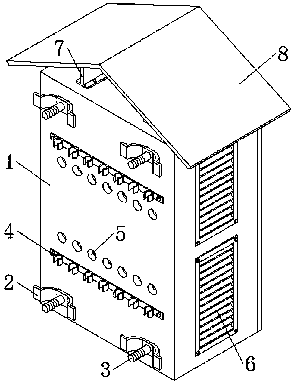
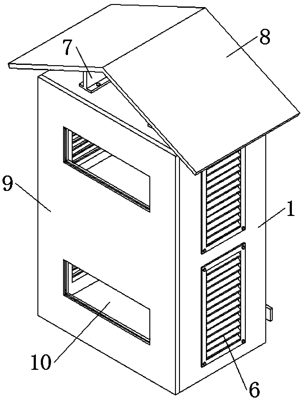
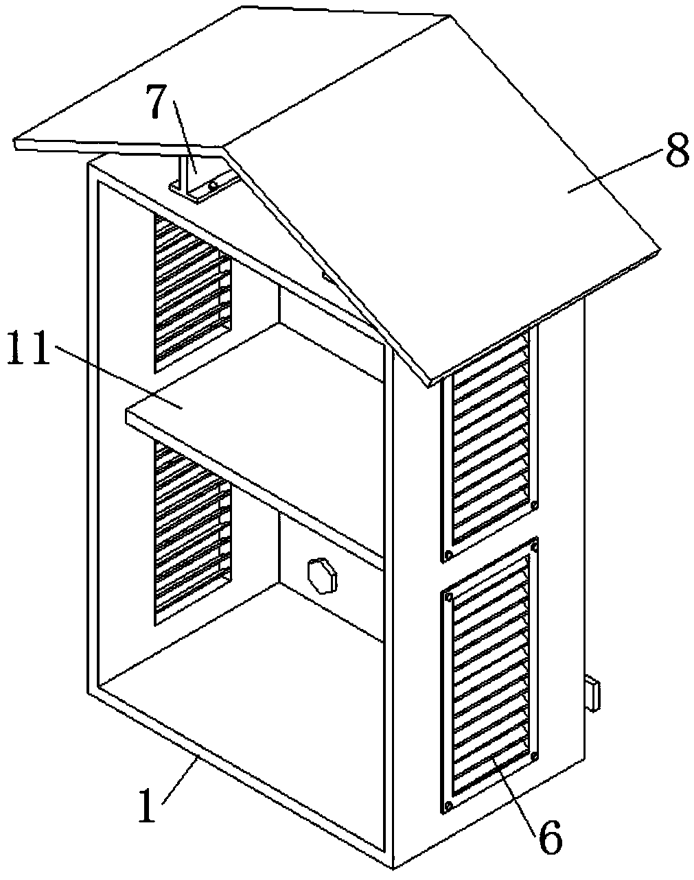
[0027] see Figure 1-5 , the present invention provides a technical solution: an indoor optoelectronic integrated optical fiber composite low-voltage power cable distribution box, including a distribution box 1, the four corners of the rear wall of the distribution box 1 are welded with elastic brackets 2, and the distribution box The four corners of the rear wall of the inner cavity of the body 1 are equipped with fixing screws 3, and the fixing screws 3 run throu...


PUM


Abstract

The invention discloses an indoor photoelectric integrated optical fiber composite low-voltage power cable distribution box in the technical field of distribution boxes, which includes a distributionbox, the four corners of the rear wall of the distribution box body are welded with elastic supports, the four corners of the rear wall of the inner cavity of the distribution box body are provided with fixing screws, and the fixing screw penetrates the middle of the elastic bracket, the rear wall of the distribution box body is transversely and symmetrically installed with rational wire bracketsthrough screws. The box comprises elastic brackets at the four corners of the rear wall of the distribution box, and the distribution box body is fixed with to wall body by fix screws in a spaced manner, so that the invention reduces the corrosion phenomenon of the wall body to the distribution box body, thereby enabling the power cable to be connected to the inner cavity of the distribution box body from the wire row hole, and through the arranged wire management bracket, the connected power cable can be limited and arranged, the confusion phenomenon of the power cable can be reduced, and themaintenance or repair of the power cable can be facilitated in the later period.

Description

technical field [0001] The invention relates to the technical field of distribution boxes, in particular to an indoor optoelectronic integrated optical fiber composite low-voltage power cable distribution box. Background technique [0002] Due to its small size, easy installation, special technical performance, fixed position, unique configuration functions, and no site restrictions, the distribution box is widely used, stable and reliable in operation, high in space utilization, small in floor space and environmentally friendly. . It is the control center that directs the various components in the power supply line to distribute electric energy reasonably. It is the control link that reliably receives the upper-end power supply and correctly feeds out the load electric energy. It is also the key to obtain whether the user is satisfied with the quality of the power supply. It is required to be assembled in closed or semiclosed metal safe by switchgear, measuring instrument,...

Claims


Application Information

Patent Timeline
Patent Type & Authority Applications(China)
IPC IPC(8): H02B1/40H02B1/56H02B1/28H02B1/30H02B1/20
Inventor 钟先杰
Owner 合肥先杰新能源科技有限公司
Learn More