An isolated charging and discharging system with bidirectional energy flow

A two-way flow, charging and discharging technology, applied in electric vehicle charging technology, control/regulation system, information technology support system, etc., can solve the problems of single application, one-way charging module, etc., to eliminate harmonic pollution and maximize utilization. The effect of high-efficiency isolation of DC/DC conversion

Pending Publication Date: 2018-12-28
珠海泰通电气技术有限公司
View PDF0 Cites 4 Cited by
  • Summary
  • Abstract
  • Description
  • Claims
  • Application Information

AI Technical Summary

Problems solved by technology

However, the existing charging modules are basically one-way, that is, only the power grid can flow to the car battery to charge the battery, and the application is relatively single

Method used


Image

  • An isolated charging and discharging system with bidirectional energy flow
  • An isolated charging and discharging system with bidirectional energy flow

Examples


Embodiment Construction

[0017] In order to make the object, technical solution and advantages of the invention clearer, the present invention will be further described in detail below in conjunction with the accompanying drawings and embodiments. It should be understood that the specific embodiments described here are only used to explain the present invention, and are not limited to the present invention.

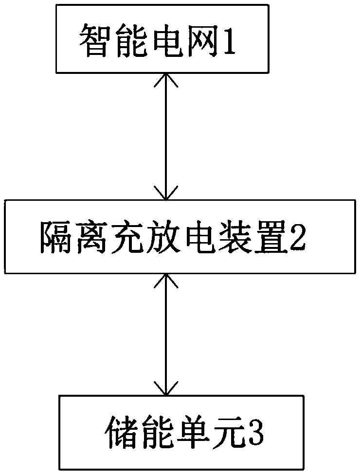
[0018] see figure 1 , an isolated charging and discharging system with two-way flow of energy in the present invention includes a smart grid 1, an isolated charging and discharging device 2, and an energy storage unit 3, and the isolated charging and discharging device 2 is used to control the smart grid 1 to output electric energy to the energy storage unit 3, or The energy storage unit 3 is controlled to output electric energy to the smart grid 1 . Wherein, the energy storage unit 3 may be an electric vehicle battery or an energy storage battery and capacitor.

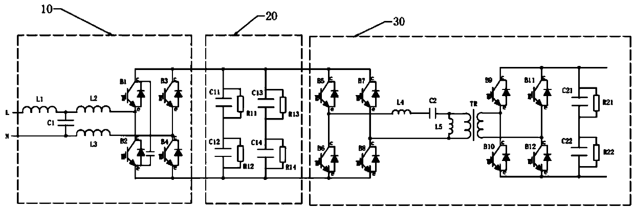
[0019] Such as figure 2 As s...


PUM


Abstract

The invention discloses an isolated charging and discharging system with bidirectional energy flow. The system includes a smart grid, an insolated charging and discharging device and an energy storageunit, and the isolated charging and discharging device is used for controlling the smart grid to output electric power to the energy storage unit, or controlling the energy storage unit to output electric energy to the smart grid. The isolated charging and discharging device comprises a PWM rectifier circuit, a first DC circuit and a DAB circuit connected in turn. The DAB circuit comprises a first inverter circuit, a resonant circuit, an isolated transformer, a second inverter circuit and a second DC circuit. The isolated charging and discharging system of the invention can be applied to electric vehicle charging and smart grid energy storage, has few components and wide output voltage range, can realize the isolated bidirectional energy flow of the power supply, and can effectively maximize the utilization rate of electric energy.

Description

【Technical field】 [0001] The invention relates to the technical field of electric vehicles, in particular to an isolated charging and discharging system with bidirectional flow of energy. 【Background technique】 [0002] In various applications such as new energy photovoltaic systems, energy storage systems, and electric vehicle charging systems, it is required that the energy in the power converter can flow in both directions, and the energy can flow from the grid to the energy storage unit such as the battery to realize the storage of electric energy. At the same time, It is also required that energy can flow from the energy storage unit to the grid or be output in the form of AC power alone, so as to realize the regulation of grid power or meet the use of power under off-grid conditions. However, the existing charging modules are basically one-way, that is, only the grid can flow to the car battery to charge the battery, and the application is relatively single. [0003] ...

Claims


Application Information

Patent Timeline
IPC IPC(8): H02M3/335H02M7/797H02J3/32H02J7/00H02J7/02
CPCH02J7/022H02J3/32H02J7/0068H02M3/33584H02M7/797H02J2207/20Y02B70/10Y02T90/167Y04S30/12
Inventor 吴亚杰
Owner 珠海泰通电气技术有限公司
Why Eureka
Try Eureka