Modularly-combined waste gas purification apparatus

An exhaust gas purification device and exhaust gas purification technology are applied in separation devices, gas treatment, transportation and packaging, etc., which can solve the problems of safety hazards in low-temperature plasma, limited adsorption capacity of activated carbon, and low photocatalytic purification efficiency, and achieve convenient and quick assembly , compact structure, convenient and quick equipment maintenance and replacement

Inactive Publication Date: 2019-01-01
AEROSPACE KAITIAN ENVIRONMENTAL TECH CO LTD
View PDF6 Cites 10 Cited by
  • Summary
  • Abstract
  • Description
  • Claims
  • Application Information

AI Technical Summary

Problems solved by technology

At present, technologies such as "photocatalysis", "activated carbon adsorption" or "low temperature plasma" are often used for treatment. There are some disadvantages in a single technology, such as the low efficiency of photocatalytic purification; the adsorption capacity of activated carbon is limited, and the adsorption material needs to be replaced regularly, which is costly. ; Low-temperature plasma has potential safety hazards, and the requirements for exhaust gas are strict
In addition, in some occasions, the exhaust gas discharged is discontinuous, there are periodic exhaust phenomena, and the concentration of exhaust gas fluctuates greatly. It is bound to cause waste when the exhaust gas concentration is low
Moreover, different types of equipment are used for different exhaust gases, and the production of non-standard equipment will undoubtedly increase the production cost. Therefore, it is particularly necessary to develop a modular combined exhaust gas purification device.

Method used


Image

  • Modularly-combined waste gas purification apparatus
  • Modularly-combined waste gas purification apparatus
  • Modularly-combined waste gas purification apparatus

Examples


Embodiment Construction

[0033] The present invention will be further described below with reference to the accompanying drawings and specific embodiments.

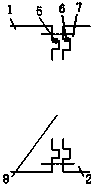
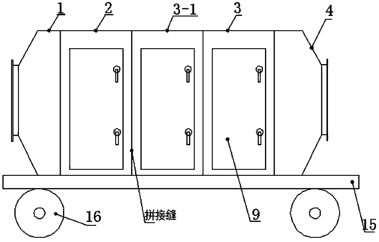
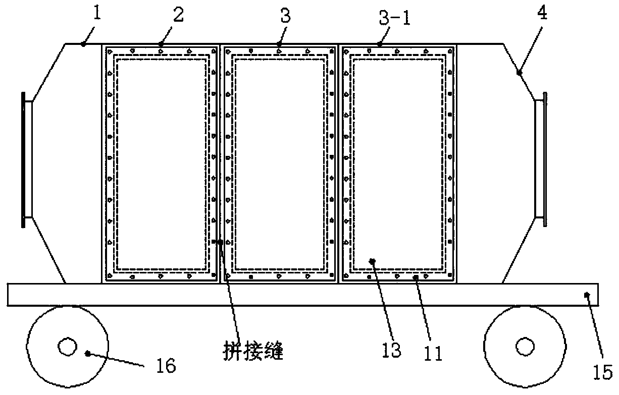
[0034] see Figure 1-Figure 8 , In one embodiment, a modular combined exhaust gas purification device is composed of a row of purification units, and the row of purification units includes an air inlet equalization section 1, a pretreatment section 2, and an exhaust gas purification section 3 connected in series in sequence And the exhaust section 4, the air inlet equalization section 1 and the pretreatment section 2, the pretreatment section 2 and the exhaust gas purification section 3, and the exhaust gas purification section 3 and the exhaust section 4 are detachably sealed and spliced ​​together. Specifically in this embodiment, the side walls where the air inlet equalization section 1 and the pretreatment section 2, the pretreatment section 2 and the exhaust gas purification section 3, and the exhaust gas purification section 3 and the exhau...


PUM


Abstract

The invention discloses a modularly-combined waste gas purification apparatus. The modularly-combined waste gas purification apparatus consists of one or multiple rows of purification units which arearranged side by side, wherein different rows of purification units are detachably spliced, each row of purification units comprises an air inlet homogenizing section, a waste gas purification sectionand an exhaust section which are successively serially connected with one another, the air inlet homogenizing section is detachably connected with the waste gas purification section in a sealing manner, the waste gas purification section is detachably connected with the exhaust section in a sealing manner, and the waste gas is successively homogenized by the air inlet homogenizing section, purified by the waste gas purification section and exhausted by virtue of an exhaust fan in the exhaust section. The modularly-combined waste gas purification apparatus provided by the invention is high inintegration degree, compact in structure, small in floor occupation space, convenient in disassembling and installation and convenient in maintenance, can be used under various working conditions by flexibly increasing or reducing modules, can efficiently treat the exhausted waste gas at any time at any place, can be widely applied to the purification of various industrial waste gas comprising theindustrial waste gas which is not continuously discharged, and can improve the applicability.

Description

technical field [0001] The invention belongs to the field of industrial waste gas purification, in particular to a modular combined waste gas purification device. Background technique [0002] In recent years, environmental pollution issues have attracted widespread attention, including industrial waste gas treatment. There are many industries that generate industrial waste gas, such as packaging and printing, petrochemical, spraying, rubber products, etc. The nature, concentration, and air volume of waste gas generated by different industries are different. Therefore, corresponding exhaust gas treatment technologies are emerging in an endless stream. At present, technologies such as "photocatalysis", "activated carbon adsorption" or "low temperature plasma" are often used for treatment. Each single technology has some drawbacks, such as low photocatalytic purification efficiency; activated carbon adsorption capacity is limited, and the adsorption material needs to be repla...

Claims


Application Information

Patent Timeline
IPC IPC(8): B01D53/00B01D53/02B01D53/32B01D53/18B01D46/00
CPCB01D53/00B01D53/02B01D53/18B01D53/32B01D2253/102B01D2221/08B01D2258/02B01D2259/818B01D46/64B01D46/88
Inventor 彭芬刘彰刘强吴卫
Owner AEROSPACE KAITIAN ENVIRONMENTAL TECH CO LTD
Why Eureka
Try Eureka