Connecting rod pin hole fine grinding equipment and crankshaft production process

A production process and connecting rod pin technology, applied in the field of crankshaft processing, can solve the problems of reduced precision, impacted production efficiency, shortened honing time, etc., to improve the use accuracy and life, improve work performance, improve surface hardness and wear resistance sexual effect

Active Publication Date: 2019-01-01
青岛锦瑞特园林工具有限公司
View PDF13 Cites 2 Cited by
  • Summary
  • Abstract
  • Description
  • Claims
  • Application Information

AI Technical Summary

Problems solved by technology

[0006] Since the work of the assembled crankshaft is affected by the precision of the connecting rod 5 and the crank 6, the traditional connecting rod fine grinding equipment can only honing a single connecting rod 5 at a time, which affects the producti

Method used


Image

  • Connecting rod pin hole fine grinding equipment and crankshaft production process
  • Connecting rod pin hole fine grinding equipment and crankshaft production process
  • Connecting rod pin hole fine grinding equipment and crankshaft production process

Examples


Example Embodiment

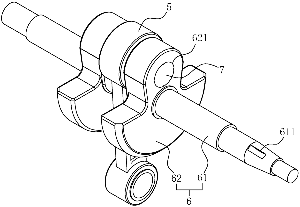
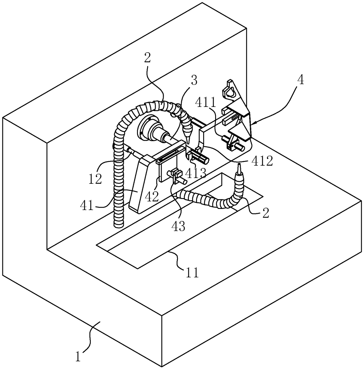
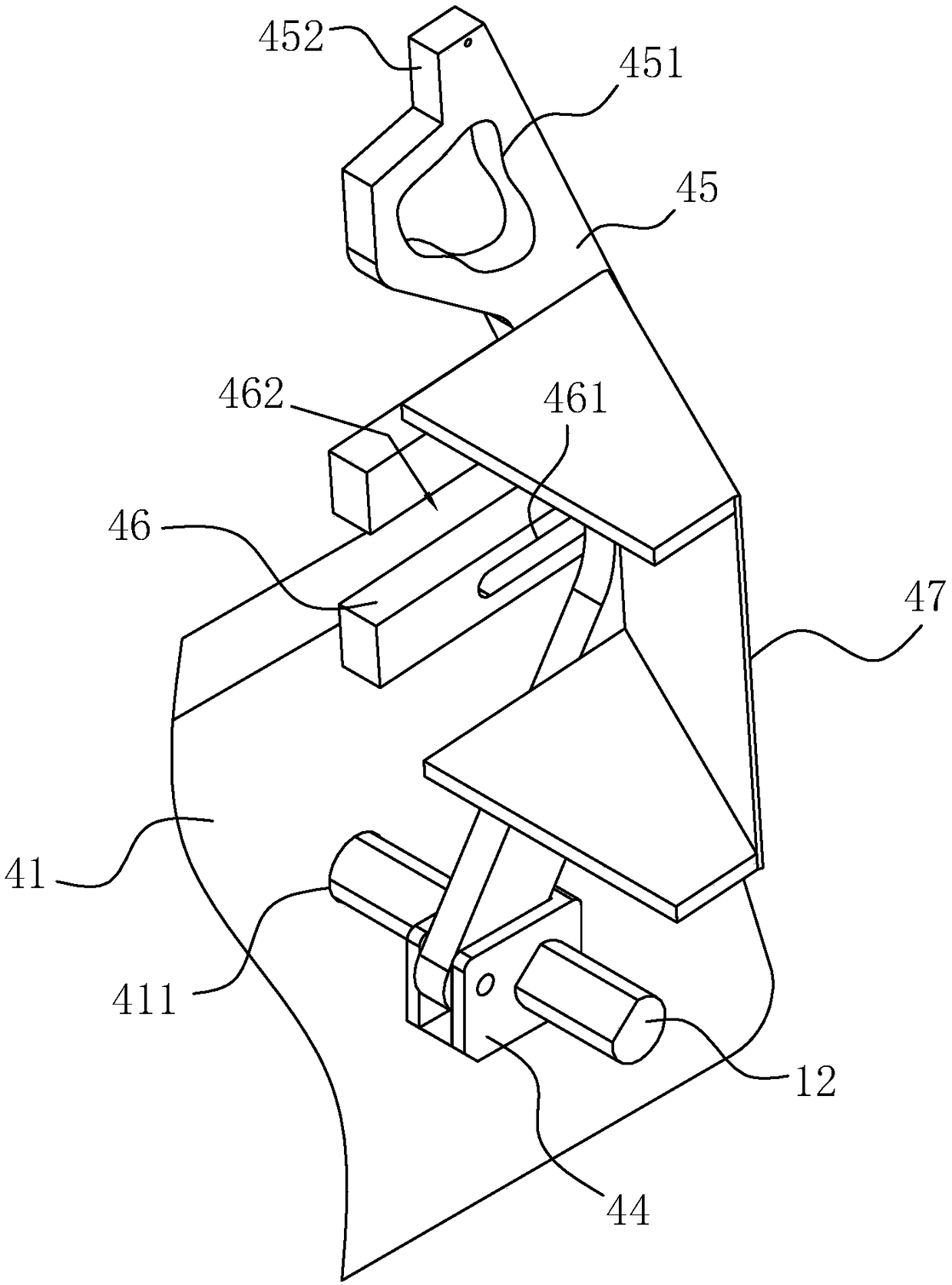
[0050] Embodiment 1: A kind of connecting rod pin hole precision grinding equipment, such as figure 2 As shown, it includes a frame 1 and a grinding shaft 3 mounted on the frame 1 for horizontal rotation. One end of the grinding shaft 3 is connected with a drive motor, and a clamping mechanism 4 is installed on the frame 1 through a support rod 12. The grinding shaft 3 Through the middle part of the clamping mechanism 4, a cooling pipe 2 for spraying cooling fluid to the end of the grinding shaft 3 is installed on the frame 1. Put the pin hole of connecting rod 5 on the grinding shaft 3

[0051] refer to figure 2 , the frame 1 is located below the grinding shaft 3 and is provided with a sump 11, the bottom of the sump 11 is connected to the external coolant barrel through a drain pipe, the coolant barrel is connected to a suction pump through a pipeline, and the suction pump The outlet is connected with the cooling pipe 2. The cooling pipe 2 can use a corrugated pipe, whi...

Example Embodiment

[0066] Embodiment two: a kind of crankshaft production technology, such as Figure 7 shown, including the following steps:

[0067] (1) Crank rough production: heat one end of 20Cr round steel with a diameter of φ20mm and a length of 25cm to 1150°C and upset, so that the round steel becomes a hemispherical blank at one end, and the heated length is 8cm. Then put the preform after upsetting in the forging die and go through the first hot forging and the second hot forging continuously. The temperature of the first hot forging is 1150°C, and the time is 5S; The hemispherical end of the blank is formed into the balance weight 62 of the crank 6 . Then use tools to remove the flash at the balance weight 62, and perform shot blasting on the workpiece to obtain the crank blank.

[0068] (2) Rough machining of the crank blank: fix the balance weight 62 of the crank blank, and process the end face of the round steel far away from the end of the balance weight 62, that is, grind the e...


PUM


Abstract

The invention discloses connecting rod pin hole fine grinding equipment and a crankshaft production process and relates to the technical field of crankshaft machining. According to the main points ofthe technical scheme, the connecting rod pin hole fine grinding equipment comprises a rack and a grinding shaft installed on the rack horizontally rotationally. A driving mechanism drive the grindingshaft is connected to one end of the grinding shaft. A cooling pipe is connected to the rack and is provided with a nozzle extending to the grinding shaft. A vertically arranged installing plate is fixed to the rack through a strut. A U-shaped groove is formed in the middle of the installing plate, and the grinding shaft can penetrate through the U-shaped groove. A jacking block and a clamping block are fixed to one end of the installing plate. The jacking block is located on one side of the U-shaped groove and extends in the axial direction of the grinding shaft. The clamping block is provided with a clamping groove. A limiting plate is connected to the other end of the installing plate. The limiting plate rotates around the axis perpendicular to the installing plate and relative to the installing plate. The end, away from the rotation axis, of the limiting plate is provided with a clamping connection part matched with the clamping groove. Through the connecting rod pin hole fine grinding equipment and the crankshaft production process, the problem of high circle jumping in the use process due to low precision of existing crankshaft machining is solved, a shaft rod of a crank is centered, fine grinding is conducted on a connecting rod, and thus precision of the crankshaft is improved.

Description

technical field [0001] The invention relates to the technical field of crankshaft processing, more specifically, it relates to a connecting rod pin hole precision grinding equipment and a crankshaft production process. Background technique [0002] The crankshaft is the main rotating part of the engine. After the connecting rod is installed, it can undertake the up and down (reciprocating) motion of the connecting rod into a circular (rotating) motion. Its material is made of carbon structural steel or ductile iron. There are two important parts: the main journal and the connecting rod neck. The head hole is connected with the cylinder piston, which is a typical slider crank mechanism. [0003] The authorized notification number is CN204458787U Chinese utility model patent, which discloses a crankshaft structure, including at least two crankshaft bodies connected together, and the two crankshaft bodies are fixedly installed together through connecting sleeves; the crankshaf...

Claims


Application Information

Patent Timeline
IPC IPC(8): B24B5/48F16C3/08
CPCB24B5/48F16C3/08
Inventor 姜汉龙
Owner 青岛锦瑞特园林工具有限公司
Why Eureka
Try Eureka