[0022] In order to make the technical means, creative features, objectives and effects of the present invention easy to understand, the present invention will be further explained below in conjunction with specific embodiments.
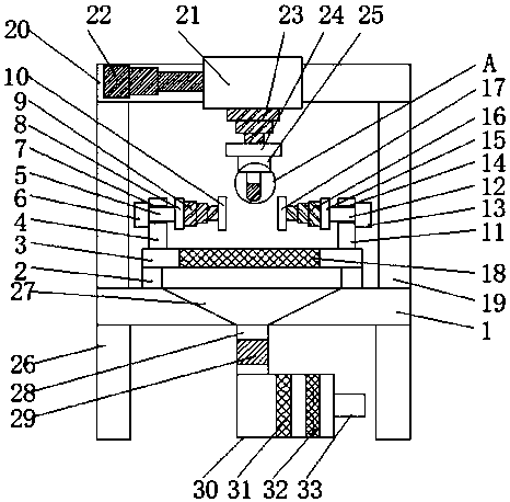
[0023] Such as Figure 1-5 As shown, a polishing device for processing precision parts includes a workbench 1, a movable rod 2 is provided on the upper end of the workbench 1, and a fifth electric telescopic rod 34 is fixed on the workbench 1, one end of the fifth electric telescopic rod 34 It is fixed to the moving rod 2, a support plate 3 is installed between the moving rods 2, and a first fixed rod 4 is fixed above the left end of the support plate 3, and a first rotating shaft 5 is horizontally arranged on the first fixed rod 4. A first rotating motor 6 is installed on the left end of the shaft 5, a first mounting plate 8 is fixed on the right end of the first rotating shaft 5, and a first electric telescopic rod 9 is fixed on the right end of the first mounting plate 8. A first clamping plate 10 is fixed at the right end, and a second fixing rod 11 is fixed above the right end of the support plate 3, a second rotating shaft 12 is provided on the second fixing rod 11, and a second rotating motor is installed at the right end of the second rotating shaft 12 13, and the left end of the second rotating shaft 12 is fixed with a second mounting plate 15, the left end of the second mounting plate 15 is fixed with a second electric telescopic rod 16, the left end of the second electric telescopic rod 16 is mounted with a second clamping plate 17, and A screen 18 is installed on the upper end surface of the support plate 3, and a support rod 19 is fixed at the upper end of the workbench 1, a cross rod 20 is fixed at the upper end of the support rod 19, and a moving table 21 is provided at the upper end of the cross rod 20, and the cross rod 20 A third electric telescopic rod 22 is fixed on the upper part. The right end of the third electric telescopic rod 22 is fixed to the mobile platform 21, the lower end of the mobile platform 21 is fixed with a fourth electric telescopic rod 23, and the lower end of the fourth electric telescopic rod 23 is fixed. The lower end of the fixed plate 24 is fixed with a third rotating motor 25, the lower end of the third rotating motor 25 is fixed with a third rotating shaft 35, the lower end of the third rotating shaft 35 is provided with a threaded hole 36, the threaded hole 36 has internal threads A connecting rod 37 is fixed, the lower end of the connecting rod 37 is fixed with a grinding head 38, and the upper end of the workbench 1 is equipped with a dust collecting hood 27, the lower end of the dust collecting hood 27 is provided with a pipe 28, and an exhaust fan 29 is installed in the pipe 28 A dust box 30 is installed at the lower end of the pipe 28. A first filter screen 31 and a second filter screen 32 are installed in the dust box 30. The second filter screen 32 is arranged at the right end of the first filter screen 31 and the right end of the dust box 30 An outlet pipe 33 is installed.
[0024] The moving rod 2 is slidably connected to the upper end surface of the worktable 1 through a sliding block, so that the fifth electric telescopic rod 34 drives the moving rod 2 to slide on the upper end surface of the worktable 1; the moving table 21 is slidably connected by the sliding block and the cross bar 20, It is convenient for the third electric telescopic rod 22 to drive the mobile platform 21 to slide on the crossbar; a first bearing 7 is installed at the connection between the first rotating shaft 5 and the first fixed rod 4, so that the first rotating motor 6 can drive the first rotating shaft 5 Rotate on the first fixed rod 4; a second bearing 14 is installed at the connection between the second rotating shaft 12 and the second fixed rod 11, so that the second rotating motor 13 can drive the second rotating shaft 12 to rotate on the second fixed rod 11 ; The fifth electric telescopic rod 34 is provided with two, which is convenient for the fifth electric telescopic rod 34 to drive the moving rod 2 to move on the workbench 1; the lower end of the workbench 1 is welded and fixed with supporting legs 26, and the supporting legs 26 are provided with four and Distributed in a rectangular shape at the lower end of the workbench 1, it is convenient for the supporting legs 26 to fix and support the workbench 1, preventing the workbench 1 from shaking; the first electric telescopic rod 9, the second electric telescopic rod 16, the third electric telescopic rod 22, and the fourth The models of the electric telescopic rod 23 and the fifth electric telescopic rod 34 are YNT-03, which is convenient for the first electric telescopic rod 9, the second electric telescopic rod 16, the third electric telescopic rod 22, the fourth electric telescopic rod 23, and the fifth electric rod. The telescopic movement of the telescopic rod 34 has a good telescopic effect; the workbench 1, the movable rod 2, the support plate 3, the first fixed rod 4, the first mounting plate 8, the second fixed rod 11, the second mounting plate 15, and the support rod 19 , The cross bar 20, the fixed plate 24, and the support leg 26 are made of stainless steel. The workbench 1, the moving rod 2, the support plate 3, the first fixed rod 4, the first mounting plate 8, the second The fixed rod 11, the second mounting plate 15, the support rod 19, the cross rod 20, the fixed plate 24, and the support leg 26 are sturdy and durable, not easily damaged, and have a long service life.
[0025] It should be noted that the present invention is a polishing device for processing precision parts. When in use, the precision parts that need to be polished are placed between the first clamping plate 10 and the second clamping plate 17, and the left end of the first clamping plate 10 is installed The right end of the first electric telescopic rod 9 and the second splint 17 is equipped with a second electric telescopic rod 16 to activate the first electric telescopic rod 9, and the first electric telescopic rod 9 drives the first splint 10 to move to the right to start the second electric telescopic rod Rod 16, the second electric telescopic rod 16 drives the second splint 17 to move to the left, the first splint 10 moves to the right, and the second splint 17 moves to the left to polish the gap between the first splint 10 and the second splint 17 The precision parts are fixed to prevent loosening. The upper end of the workbench 1 is equipped with a moving rod 2, and the workbench 1 is fixed with a fifth electric telescopic rod 34. There are two fifth electric telescopic rods 34. One end is fixed to the moving rod 2. The moving rod 2 is slidably connected to the upper end surface of the worktable 1 through a sliding block, and the fifth electric telescopic rod 34 is activated. The fifth electric telescopic rod 34 drives the moving rod 2 to move on the worktable 1, thereby Drive the precision parts that need to be polished to move. A moving table 21 is installed on the cross bar 20. The moving table 21 is slidably connected to the cross bar 20 by a sliding block. The lower end of the moving table 21 is fixed with a fourth electric telescopic rod 23. A fixing plate 24 is installed at the lower end of the rod 23, a third rotating electric machine 34 is fixed at the lower end of the fixing plate 24, a third rotating shaft 35 is installed at the lower end of the third rotating electric machine 34, and a threaded hole is opened on the lower end of the third rotating shaft 35 36. A connecting rod 37 is fixed on the internal thread of the threaded hole 36. A grinding head 38 is fixed at the lower end of the connecting rod 37 to facilitate the replacement of different types of grinding heads 38 as needed. A third electric telescopic rod 22 is fixed on the cross rod 20. The right end of the electric telescopic rod 22 is fixed to the mobile platform 21, the fourth electric telescopic rod 23 is activated, and the fourth electric telescopic rod 23 drives the fixed plate 24, the third rotating motor 34, the third rotating 35, the connecting rod 37, and the grinding head 38 Move up and down to start the third rotating motor 22. The moving table 21 driven by the third rotating motor 22 moves left and right on the cross bar 20 to adjust the position of the grinding head 38. At the same time, the third rotating motor 34 is started and the third rotating motor 34 drives The third rotating shaft 35 rotates, and the third rotating motor 35 drives the connecting rod 37 and the grinding head 38 to rotate to polish the precision parts fixed between the first clamping plate 10 and the second clamping plate 17. The left end of the first electric telescopic rod 9 A first mounting plate 8 is installed, and a second mounting plate 15 is installed on the right end of the second electric telescopic rod 16, and the first rotating motor 6 is started at the same time. The first rotating motor 6 rotates to drive the first rotating shaft 5 to rotate, thereby driving the first The mounting plate 8, the first electric telescopic rod 9, and the first splint 10 rotate, and at the same time the second rotating motor 13 is started, and the second rotating motor 13 drives the second rotating shaft 12 to rotate, thereby driving the second mounting plate 15, the second electric telescopic The rod 16 and the second clamping plate 17 rotate, and the first clamping plate 10 and the second clamping plate 17 rotate, thereby driving the precision parts to rotate, which is convenient for grinding The head 38 polishes the precision parts with good polishing effect. The support plate 3 is provided with a screen 18, the upper end of the workbench 1 is installed with a dust collecting cover 27, and the lower end of the dust collecting cover 27 is provided with a pipe 28, which is installed in the pipe 28 There is an exhaust fan 29. A dust box 30 is installed at the lower end of the pipe 28. A first filter 31 and a second filter 32 are installed in the dust box 30. The second filter 32 is arranged at the right end of the first filter 31 and removes dust. An air outlet pipe 33 is installed at the right end of the box 30, and the exhaust fan 29 in the pipe 28 is activated. The exhaust fan 29 draws the dust produced by the grinding head 38 to the precision parts into the dust cover 27, and enters the dust cover 27 through the pipe 28. In the dust removal box 30, the first filter mesh 31 and the second filter mesh 32 in the dust removal box 30 filter out dust in the wind, and the wind blows out from the air outlet pipe 33.
[0026] The basic principles and main features and advantages of the present invention have been shown and described above. Those skilled in the industry should understand that the present invention is not limited by the foregoing embodiments. The foregoing embodiments and descriptions only illustrate the principles of the present invention. Without departing from the spirit and scope of the present invention, the present invention may have Various changes and improvements, these changes and improvements fall within the scope of the claimed invention. The scope of protection claimed by the present invention is defined by the appended claims and their equivalents.