Twine knotter

The technology of a knotter and a knotting nozzle is applied in the field of rope binding knotters, which can solve the problems of insufficient rope binding adaptability and unstable performance of a rope clamping mechanism, and achieve the effects of simple structure, low cost and reduced loss.

Active Publication Date: 2019-01-01
GUANGXI UNIV
View PDF5 Cites 3 Cited by
  • Summary
  • Abstract
  • Description
  • Claims
  • Application Information

AI Technical Summary

Problems solved by technology

[0004] The object of the present invention is to provide a rope knotter, which is used to solve the problems of insufficient adaptability of the rope and unstable performance of the rope clamping mechanism of the existing rope knotter

Method used


Image

  • Twine knotter
  • Twine knotter
  • Twine knotter

Examples


Embodiment Construction

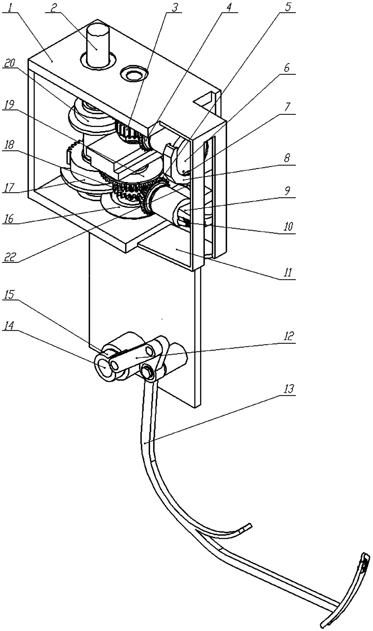
[0032] The specific implementation of the invention will be further described below in conjunction with the accompanying drawings.

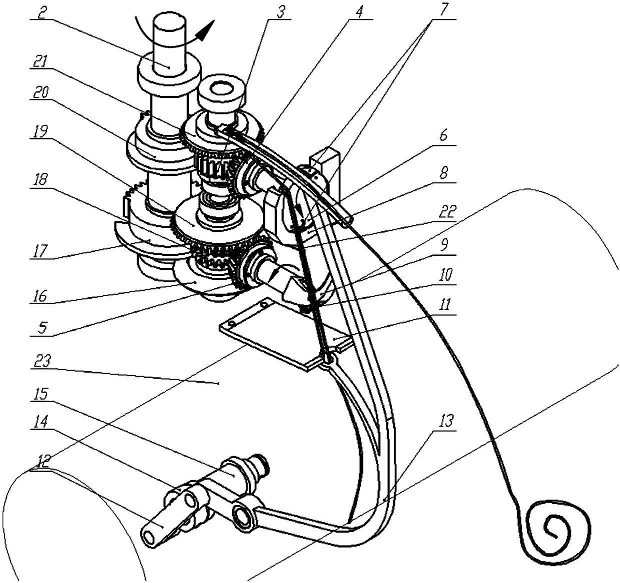
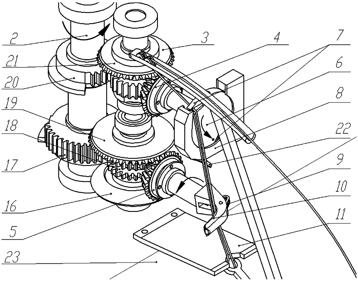
[0033] like figure 1 As shown, a rope knotter includes a frame 1, a rope feeding mechanism, a rope clamping mechanism, and a knotting mechanism.

[0034] The rope-feeding mechanism comprises a rope-feeding rotating shaft 14, a crank 15, a rope-feeding rod 13, a connecting rod 12, a driving shaft 2, a driving bevel gear and a driven bevel gear; Frame 1 bottom, crank 15 is fixedly installed on the left end of rope-feeding rotating shaft 14, and one end of rope-feeding bar 13 is rotatably installed on the bottom of frame 1, and crank 15 and rope-feeding bar 13 are positioned at the same side of frame 1, and connecting rod 12 One end is rotatably installed on the crank 15, and the other end of the crank 15 is rotatably connected with the end of the connecting end of the rope-feeding rod 13; when the rope-feeding rotating shaft 14 drives the crank 15...


PUM


Abstract

The invention discloses a twine knotter, belonging to the field of binding machinery and equipment. The twine knotter comprises a twine feeding mechanism, a twine clamping mechanism and a knotting mechanism. The twine feeding mechanism comprises a twine feeding rod and a twine feeding driving unit, the twine feeding driving unit can make the twine feeding rod swing periodically and feed into the twine clamping mechanism, the twine clamping mechanism comprises a rotary table, a twine clamping rotating shaft, two clamping plates, two torsion springs and a twine clamping driving unit, the rotarytable is rotatably installed at the front end of the twine clamping rotating shaft and is located in an accommodation portion of a frame through the twine clamping rotating shaft, the twine clamping driving unit drives the twine clamping rotating shaft to rotate intermittently through a twine clamping bevel gear, the knotting mechanism comprises a knotting nozzle, a knotting clip, a knotting bevelgear, a twine cutter and a knotting driving unit, and the knotting driving unit can drive a knotting rotating shaft to rotate intermittently and open or close the knotting clip. The invention provides the twine knotter which is used for solving the problems that the existing twine knotter is insufficient in adaptability to twines and the performance of the twine clamping mechanism is unstable.

Description

technical field [0001] The invention belongs to the field of binding mechanical equipment, in particular to a rope knotter. Background technique [0002] Rope knotters are used primarily in large rectangular balers for the movement of straw, hay, silage and similar materials and in recycling applications such as for baling paper, fabric, sheet metal and the like. A binding or strapping mechanism equipped with such a cord knotter may also be part of a packaging plant for cording bags, bundles or bales of material suitable therefor. The main function of the knotter is to clamp the bundled rope sent by the rope feeding mechanism, and complete the rope-taking, clamping, winding, biting, cutting and tripping actions required for bundling and knotting. At present, knotters and their parts cannot be produced independently in China, and are almost completely dependent on imports. [0003] The D-type knotter produced by German RASSPE company and the C-type knotter produced by Klaas...

Claims


Application Information

Patent Timeline
IPC IPC(8): B65B13/26A01F15/08
CPCA01F15/08B65B13/26
Inventor 蒙艳玫陈昊韦俊东崔耀升李怡哲赵秦川
Owner GUANGXI UNIV
Why Eureka
Try Eureka