Hydropower station tail water dredging method

A hydropower station and tail water technology, which is applied in the direction of earth mover/shovel, mechanically driven excavator/dredger, construction, etc., can solve the problems of hydropower station tail water silt accumulation, etc., achieve a high degree of automation and improve dredging Efficiency, the effect of avoiding high-intensity labor

Inactive Publication Date: 2019-01-01
王晓冬
View PDF6 Cites 0 Cited by
  • Summary
  • Abstract
  • Description
  • Claims
  • Application Information

AI Technical Summary

Problems solved by technology

[0004] The purpose of the present invention is to solve the problem of sludge accumulation in the tail water of a hydropower station, and then provide a method for dredging the tail water of a hydropower station

Method used


Image

  • Hydropower station tail water dredging method
  • Hydropower station tail water dredging method
  • Hydropower station tail water dredging method

Examples


specific Embodiment approach 1

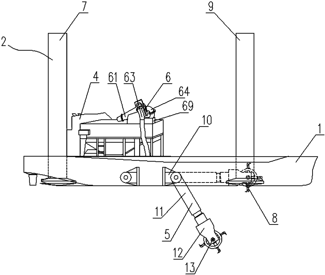
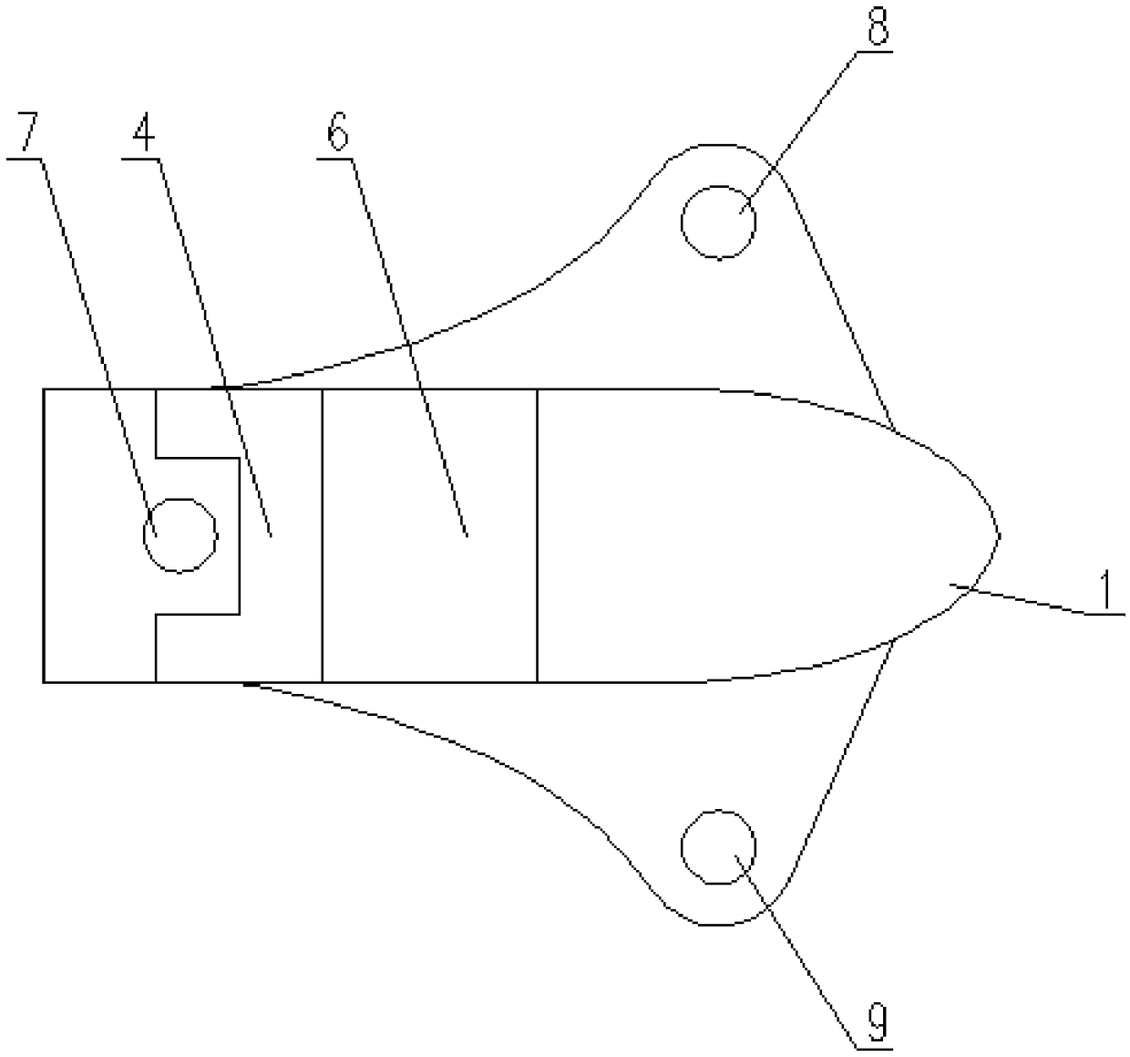
[0040] Specific implementation mode one: combine figure 1 and Figure 10Describe this embodiment mode, a kind of hydropower station tail water dredging device of this embodiment comprises dredging hull 1, pile leg 2, driving control room 4, silt digging device 5 and silt extracting device 6, described dredging hull 1 is an axisymmetric structure, the central axis of the dredging hull 1 is set along the length of the ship, and three legs 2 are arranged on the dredging hull 1, and the three legs 2 can be lifted and installed on the dredging hull 1. The three legs 2 include The first leg 7 at the stern of the dredging hull 1, the second leg 8 and the third leg 9 at the bow of the dredging hull 1, the first leg 7 is located at the central axis of the dredging hull 1 Above, the second leg 8 and the third leg 9 are located on both sides of the central axis of the dredging hull 1 and arranged symmetrically, and the line connecting the second leg 8 and the third leg 9 is perpendicula...

specific Embodiment approach 2

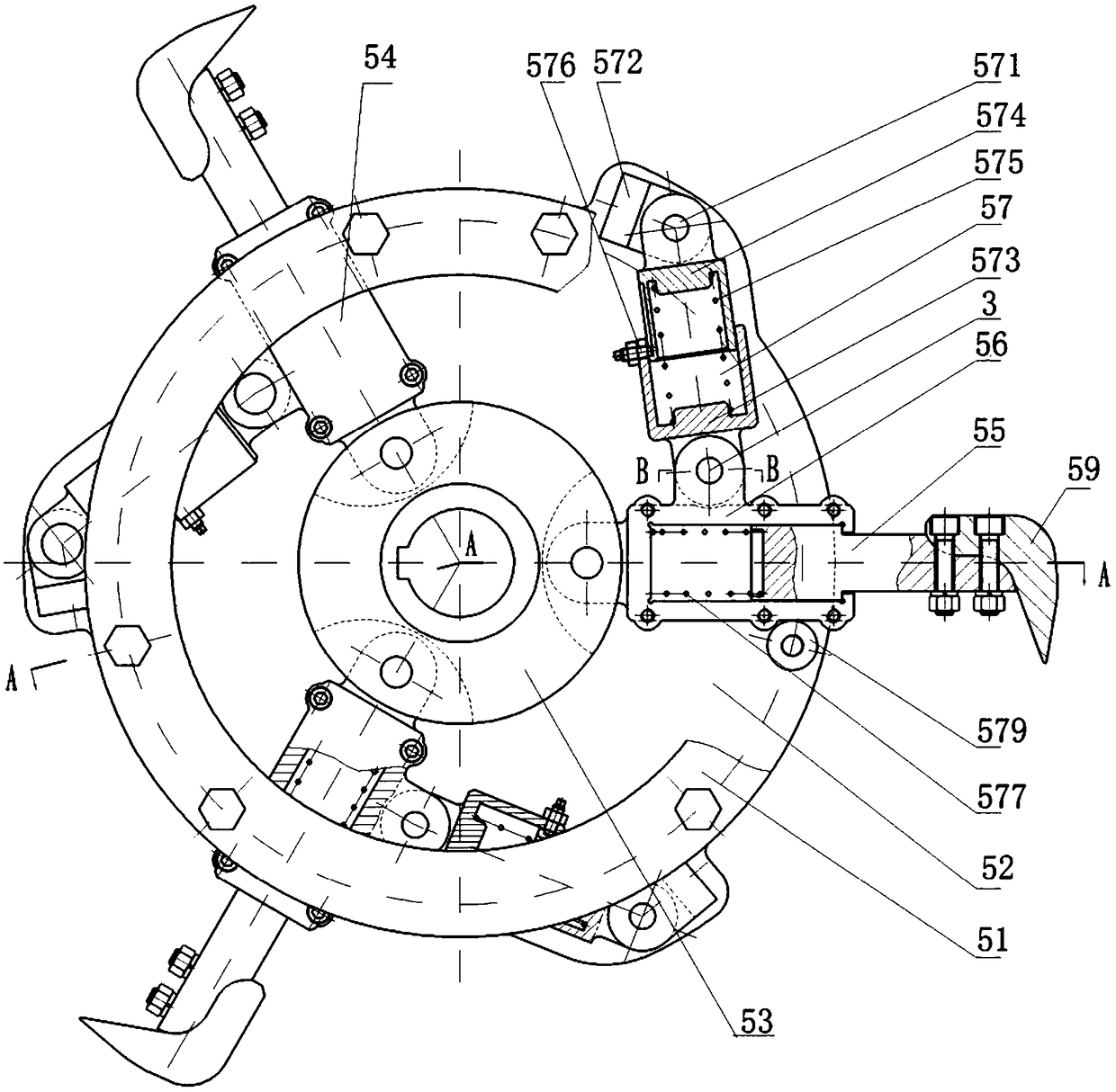
[0045] Specific implementation mode two: combination figure 1 and Figure 10 Describe this embodiment, a kind of hydropower station tailwater dredging device of this embodiment, described mud crushing digging mechanism 54 comprises sliding knife bar 55, knife bar seat 56 and telescopic device 57, and knife bar seat 56 passes knife bar Seat connecting pin 58 is installed on the central disc 53 in rotation, the inner end of sliding knife bar 55 is installed in the knife bar seat 56, and the outer end of sliding knife bar 55 is equipped with stirring cutter 59, and one end of described telescopic device 57 passes through Connecting pin 3 is connected on the outer wall of cutter bar seat 56, and the other end of telescoping device 57 is connected with pin seat 572 by telescoping device connecting pin 571, and pin seat 572 is fixedly installed on the inner mounting plate 52; Described telescoping device 57 comprises The outer telescopic sleeve 573 and the inner telescopic sleeve 5...

specific Embodiment approach 3

[0046] Specific implementation mode three: combination figure 1 and Figure 10 Describe this embodiment, a kind of hydropower station tail water dredging device of this embodiment, described outer telescoping sleeve 573 edge is installed sliding pin 576, described sliding pin 576 is connected with nut, described inner telescopic sleeve 574 A groove is opened on the outer wall along its generatrix, and the end of the sliding pin 576 passes through the outer telescopic sleeve 573 to slide in the groove. In this way, the sliding pin 576 drives the outer telescopic sleeve 573 to slide in the groove of the inner telescopic sleeve 574 , reducing the rotational movement between the outer telescopic sleeve 573 and the inner telescopic sleeve 574 and increasing the service life of the telescopic device 57 .


PUM


Abstract

The invention discloses a hydropower station tail water dredging method and belongs to the technical field of water conservancy and hydropower equipment. By means of the hydropower station tail waterdredging method, the problem about accumulation of hydropower station tail water is solved. The hydropower station tail water dredging method has the steps of 1, carrying out sludge excavation operation for hydropower station tail water accumulation; 2, carrying out sludge pumping for hydropower station tail water accumulation; and 3, separating sludge from tail water in a sludge storage tank. According to the hydropower station tail water dredging method, removed sludge is subjected to water filtering inside the sludge storage tank, water filtered out flows back to water of a hydropower station, and thus the purpose that hydropower station tail water is prevented from being wasted is achieved.

Description

technical field [0001] The invention relates to a tail water dredging method of a hydropower station, belonging to the technical field of water conservancy and hydropower equipment. Background technique [0002] After the completion of the hydropower station, the downstream channel of the dam area has experienced many times of flood discharge, washing and digging damage, and the influence of various hydraulic structures and terrain will cause a large amount of siltation in the tailrace channel and the downstream channel, thereby increasing the power generation capacity. The tailwater level affects the output of the unit. In view of these situations, strengthening the management of the tail water dredging project is of great significance for controlling the tail water level of power generation and improving the efficiency of power generation. [0003] The implementation of the excavation project for the tail water of the hydropower station can effectively reduce the river bo...

Claims


Application Information

Patent Timeline
Patent Type & Authority Applications(China)
IPC IPC(8): E02F5/28E02F3/88E02F3/92E02F7/04E02F9/06
CPCE02F3/885E02F3/9237E02F5/28E02F5/282E02F7/04E02F9/062
Inventor 王晓冬
Owner 王晓冬
Why Eureka
Try Eureka