Silt breaking and excavating mechanism for hydropower station tail water desilting
A hydropower station and sludge technology, applied in the field of sludge crushing and excavation mechanism, can solve the problems of hydropower station tail water sludge accumulation and other problems, achieve high automation, improve dredging efficiency, and avoid short-term deterioration of water quality
- Summary
- Abstract
- Description
- Claims
- Application Information
AI Technical Summary
Problems solved by technology
Method used
Image
Examples
specific Embodiment approach 1
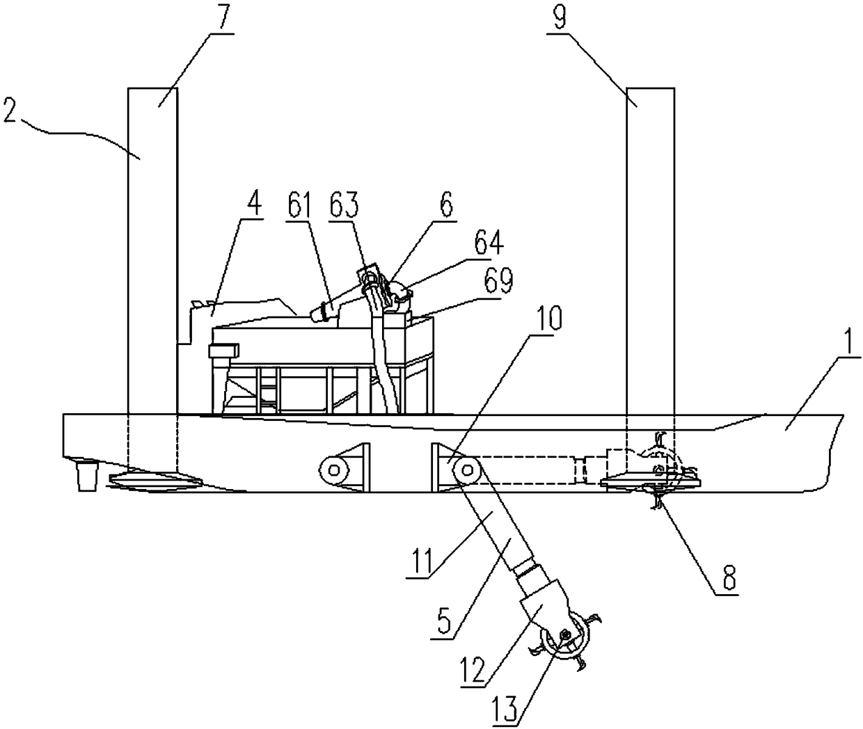
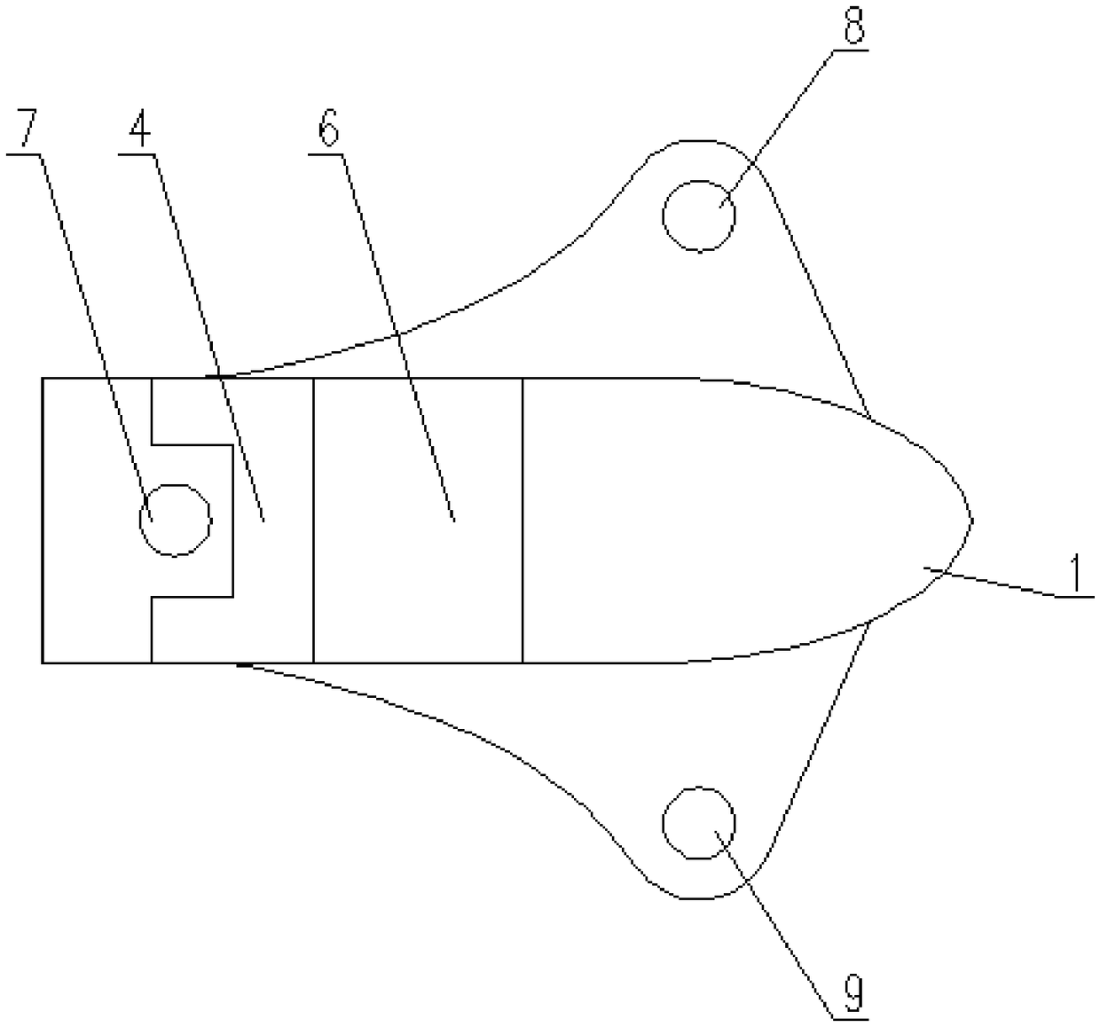
[0040] Specific implementation mode one: combine figure 1 and Figure 10Describe this embodiment mode, a kind of hydropower station tail water dredging device of this embodiment comprises dredging hull 1, pile leg 2, driving control room 4, silt digging device 5 and silt extracting device 6, described dredging hull 1 is an axisymmetric structure, the central axis of the dredging hull 1 is set along the length of the ship, and three legs 2 are arranged on the dredging hull 1, and the three legs 2 can be lifted and installed on the dredging hull 1. The three legs 2 include The first leg 7 at the stern of the dredging hull 1, the second leg 8 and the third leg 9 at the bow of the dredging hull 1, the first leg 7 is located at the central axis of the dredging hull 1 Above, the second leg 8 and the third leg 9 are located on both sides of the central axis of the dredging hull 1 and arranged symmetrically, and the line connecting the second leg 8 and the third leg 9 is perpendicula...
specific Embodiment approach 2
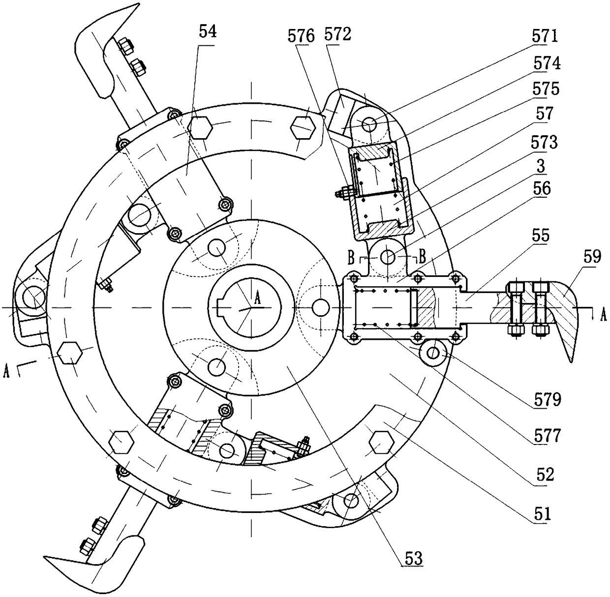
[0045] Specific implementation mode two: combination figure 1 and Figure 10 Describe this embodiment, a kind of sludge crushing and excavating mechanism used for hydropower station tail water dredging in this embodiment includes a sliding knife bar 55, a knife bar seat 56 and a telescopic device 57, and the knife bar seat 56 is connected by a knife bar seat connecting pin 58 Rotation is installed on the central disc 53, the inner end of the sliding knife bar 55 is installed in the knife bar seat 56, and the outer end of the sliding knife bar 55 is equipped with a stirring knife 59, and one end of the telescopic device 57 is connected by the connecting pin 3 On the outer wall of the knife bar seat 56, the other end of the telescopic device 57 is connected with the pin seat 572 through the telescopic device connection pin 571, and the pin seat 572 is fixedly installed on the inner mounting plate 52; the telescopic device 57 includes an outer telescopic sleeve 573 and the inner...
specific Embodiment approach 3
[0046] Specific implementation mode three: combination figure 1 and Figure 10 Describe this embodiment mode, a kind of sludge crushing and excavating mechanism used for hydropower station tail water dredging in this embodiment mode, the sliding pin 576 is installed on the edge of the outer telescopic sleeve 573, and the nut is connected to the sliding pin 576. A groove is opened on the outer wall of the inner telescopic sleeve 574 along its generatrix, and the end of the sliding pin 576 passes through the outer telescopic sleeve 573 to slide in the groove. In this way, the sliding pin 576 drives the outer telescopic sleeve 573 to slide in the groove of the inner telescopic sleeve 574 , reducing the rotational movement between the outer telescopic sleeve 573 and the inner telescopic sleeve 574 and increasing the service life of the telescopic device 57 .
PUM
 Abstract
Description
Claims
Application Information
 - R&D
- Intellectual Property
- Life Sciences
- Materials
- Tech Scout
- Unparalleled Data Quality
- Higher Quality Content
- 60% Fewer Hallucinations
Browse by: Latest US Patents, China's latest patents, Technical Efficacy Thesaurus, Application Domain, Technology Topic, Popular Technical Reports.
© 2025 PatSnap. All rights reserved.Legal|Privacy policy|Modern Slavery Act Transparency Statement|Sitemap|About US| Contact US: help@patsnap.com


