Dry type geothermal cable system with automatic over-current protection function

A technology of overcurrent protection and cable system, applied in the field of geothermal heating, can solve the problems of poor sealing, complicated construction process, irreparable problems, etc., and achieve the effect of simple structure, convenient use, and avoiding heat loss

Inactive Publication Date: 2019-01-01
XIAN GAIWO THERMAL ENERGY TECH
View PDF0 Cites 0 Cited by
  • Summary
  • Abstract
  • Description
  • Claims
  • Application Information

AI Technical Summary

Problems solved by technology

[0002] The current geothermal cable electric heating technology, its laying method is mainly wet laying method buried under cement, the structure of geothermal cable is mainly based on heating wire, single-layer insulation, single-layer shielding + ground wire, and the construction method is mainly In order to lay the heat insulation layer, steel wire mesh, geothermal cable, over-temperature protection temperature sensor, cement mortar + ground decoration layer, the laying and construction process is complicated, and due to the large construction site, there are few over-temperature protection temperature measurement sensors. , can not play the role of over-temperature protection, and because the geothermal cable and over-temperature protection temperature sensor are not well sealed during the construction process, the failure rate is high. Once damaged, it will be irreparable and there is no replacement. In order to solve these problems, some manufacturers have launched In the current dry laying method, the geothermal cable still uses the same products as the wet laying method, and the laying method is too simple, but the cement layer is canceled, and the ground decoration layer can only be the floor, which is limited. This type of dry laying method cannot be used in the living room, bathroom, kitchen and other places where tiles need to be installed in the family

Method used


Image

  • Dry type geothermal cable system with automatic over-current protection function
  • Dry type geothermal cable system with automatic over-current protection function
  • Dry type geothermal cable system with automatic over-current protection function

Examples


Embodiment Construction

[0020] The following will clearly and completely describe the technical solutions in the embodiments of the present invention with reference to the accompanying drawings in the embodiments of the present invention. Obviously, the described embodiments are only some, not all, embodiments of the present invention. Based on the embodiments of the present invention, all other embodiments obtained by persons of ordinary skill in the art without creative efforts fall within the protection scope of the present invention.

[0021] The specific embodiment of the present invention will be further described below in conjunction with accompanying drawing:

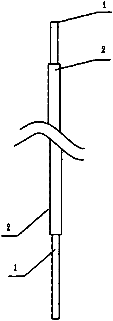
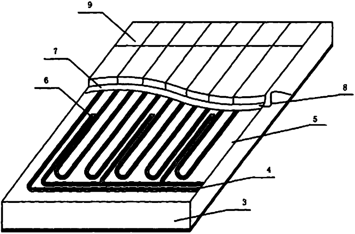
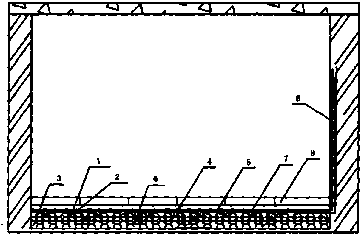
[0022] see figure 1 with figure 2 with image 3 , the present invention includes a heat insulation layer laid on the ground, the surface of the heat insulation layer is provided with a groove 4 for placing geothermal cables, a heat conduction layer 5 is embedded in the groove of the heat insulation layer, and a heat conduction layer...


PUM


Abstract

The invention relates to a dry type geothermal cable system with an automatic over-current protection function, and belongs to the field of geothermal heating. The system comprises a heat insulation layer paved on the ground, wherein the surface of the heat insulation layer is provided with a groove used for containing a geothermal cable; a heat-conducting layer is embedded into the groove of theheat insulation layer, and the geothermal cable is laid in the groove with the embedded heat-conducting layer, a current detection device is arranged in the groove with the embedded heat-conducting layer, an aluminum plate is laid above the heat-conducting layer, and a grounding wire is connected to the aluminum plate, a decoration layer is laid on the aluminum plate, and the grounding wire and the geothermal cable are connected with a power supply; the current detection device is connected with a comparison circuit, and the comparison circuit is connected with the power switch, a preset temperature upper limit value is stored in the comparison circuit; the geothermal cable comprises a heating wire; and an insulating layer is wrapped outside the heating wire.

Description

technical field [0001] The invention relates to the technical field of geothermal heating, in particular to a dry-type geothermal cable system with automatic overcurrent protection. Background technique [0002] The current geothermal cable electric heating technology, its laying method is mainly wet laying method buried under cement, the structure of geothermal cable is mainly based on heating wire, single-layer insulation, single-layer shielding + ground wire, and the construction method is mainly In order to lay the heat insulation layer, steel wire mesh, geothermal cable, over-temperature protection temperature sensor, cement mortar + ground decoration layer, the laying and construction process is complicated, and due to the large construction site, there are few over-temperature protection temperature measurement sensors. , can not play the role of over-temperature protection, and because the geothermal cable and over-temperature protection temperature sensor are not we...

Claims


Application Information

Patent Timeline
IPC IPC(8): F24D13/02F24D19/10
CPCF24D13/024F24D19/1096F24D2200/08F24D2220/042Y02B10/40
Inventor 强弱
Owner XIAN GAIWO THERMAL ENERGY TECH
Why Eureka
Try Eureka