
Telescopic oil level sensor device

An oil level sensor and an integrated technology, applied in the field of oil level sensor devices and retractable oil level sensor devices, can solve the problem that the oil at the bottom of the fuel tank cannot be used, cannot truly reflect the oil volume of the fuel tank, and the oil level sensor has a single function and other issues to achieve the effect of light weight, light weight and cost reduction

Pending Publication Date: 2019-01-01
BEIHANG UNIV
View PDF3 Cites 1 Cited by
  • Summary
  • Abstract
  • Description
  • Claims
  • Application Information

AI Technical Summary

Problems solved by technology

At present, the oil level sensor has the following problems and adjustments: First, the oil level sensor is prone to corrosion failure due to its long-term work in the oil and the harsh environment of use
Secondly, the ordinary oil level sensor has a single function and does not have the functions of oil absorption and oil return
Again, the versatility is poor, and it is often necessary to design sensing tubes of different lengths according to different fuel tank heights, resulting in multiple models of products
In addition, in order to avoid collision between the fuel level sensor and the bottom of the fuel tank due to vehicle vibration, the length of the sensor is often shorter than the height of the fuel tank, which cannot truly reflect the amount of fuel in the fuel tank, and also makes the oil at the bottom of the fuel tank unusable
For the widely used magnetic switch oil level sensor, the metal sensing tube will have a certain impact on the magnetic float, resulting in a decrease in measurement accuracy

Method used


Image

  • Telescopic oil level sensor device
  • Telescopic oil level sensor device

Examples


Embodiment Construction

[0036] Below in conjunction with accompanying drawing, the embodiment of the present invention is described in further detail:

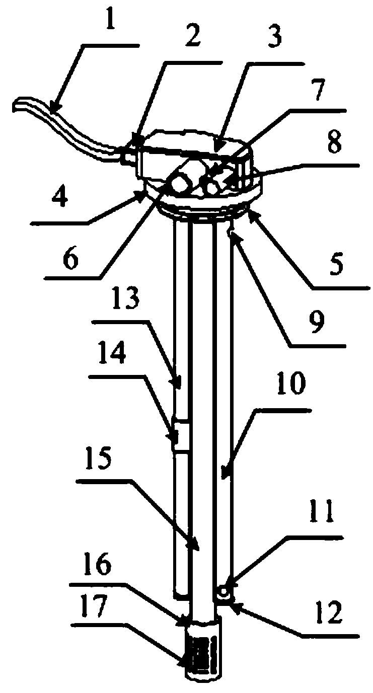
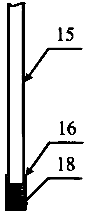
[0037] as attached figure 1 And attached figure 2 As shown, a retractable oil level sensor device of the present invention includes the following parts:

[0038]Signal cable 1, cable interface 2, electrical box 3, mounting flange 4, sealing ring 5, oil suction pipe interface 6, exhaust pipe interface 7, oil return pipe interface 8, exhaust hole 9, oil return pipe 10, oil return port 11 , blocking cover 12, induction tube 13, oil float 14, oil suction pipe 15, filter screen cover 16, filter screen 17, spring 18; the relationship between them is: signal cable 1 is connected to electrical box 3 through cable interface 2, electrical appliance The box 3 is located on the upper part of the installation flange 4, and the installation flange 4 is provided with a sealing ring 5; the oil suction pipe interface 6, the exhaust pipe interface 7 and the oil ret...


PUM


Abstract

At present, an oil level sensor has the defects of poor corrosion resistance, poor size universality, single function and the like, and aiming to solve the problem, the invention provides a telescopicoil level sensor device. The telescopic oil level sensor device comprises a signal cable, a cable interface, an electric appliance box, a mounting flange, a sealing ring, an oil suction pipe connector, an exhaust pipe connector, an oil return pipe connector, an exhaust hole, an oil return pipe, an oil return port, a plug cover, an induction pipe, an oil floater, an oil suction pipe, a filter screen cover, a filter screen and a spring, so that the functions of oil absorption, oil return and oil quantity measurement are integrated; the filter screen cover, the filter screen, the spring and theplug cover form an elastic movable device to realize direct contact with the bottom of the oil tank, so that the sensor device is telescopic and adjustable in length and is suitable for oil boxes withdifferent heights; the oil liquid at the bottom of the oil tank is fully sucked and utilized, the oil liquid at the bottom of the oil tank is circulated and replaced, and fuel waste is avoided, the formation of a bottom oil liquid deposit layer is prevented; and the characteristics of light weight, universality and multiple functions are realized, and a very wide application prospect is achieved.

Description

technical field [0001] The invention relates to an oil level sensor device, in particular to a retractable oil level sensor device, which belongs to the field of oil level sensor design and manufacture. Background technique [0002] The fuel level sensor is an important part of equipment powered by internal combustion engines such as automobiles and ships. Its main function is to detect the remaining fuel in the fuel tank and transmit the signal to the dashboard. At present, the oil level sensor has the following problems and adjustments: First, the oil level sensor is prone to corrosion failure due to its long-term work in the oil and the harsh environment of use. Secondly, the ordinary oil level sensor has a single function and does not have the functions of oil absorption and oil return. Again, the versatility is poor, and it is often necessary to design sensing tubes of different lengths according to different fuel tank heights, thereby producing multiple models of prod...

Claims


Application Information

Patent Timeline
Patent Type & Authority Applications(China)
IPC IPC(8): G01F23/72
CPCG01F23/72
Inventor 李立军孙凌玉
Owner BEIHANG UNIV
Learn More