Eureka AIR delivers breakthrough ideas for toughest innovation challenges, trusted by R&D personnel around the world.

Tunable liquid crystal laser based on SU8 grating and manufacturing method thereof

A manufacturing method and laser technology, applied in the direction of lasers, laser parts, phonon exciters, etc., can solve the problems of liquid crystal molecular helical arrangement being easily destroyed, the intensity of outgoing laser light is weak, and the output effect of wavelength tuning is unstable, etc. The effect of integration, stable wavelength tuning output, and convenient method

Inactive Publication Date: 2019-01-01
SHENYANG LIGONG UNIV
View PDF5 Cites 0 Cited by
  • Summary
  • Abstract
  • Description
  • Claims
  • Application Information

AI Technical Summary

Problems solved by technology

[0002] Liquid crystal lasers have the advantages of no need for additional resonators, small size, low cost, easy availability, simple structure, and wide tuning range. The output laser intensity is weak
The AC voltage is applied from the upper and lower ITO electrodes to form an electric field parallel to the helical axis. Under the action of the electric field, the helical arrangement of the liquid crystal molecules is easily destroyed, resulting in the shutdown of the outgoing laser, which in turn leads to unstable wavelength tuning output.

Method used


Image

  • Tunable liquid crystal laser based on SU8 grating and manufacturing method thereof
  • Tunable liquid crystal laser based on SU8 grating and manufacturing method thereof

Examples


Embodiment Construction

[0018] The present invention will be further described in detail below with reference to the drawings and embodiments.

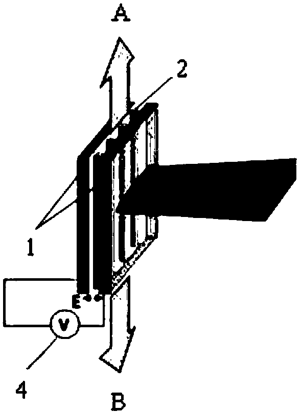
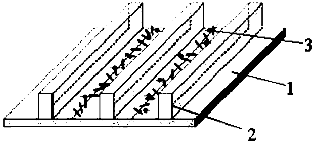
[0019] Such as figure 1 with figure 2 As shown, a tunable liquid crystal laser based on an SU8 grating includes an ITO glass substrate 1, an SU8 grating 2 is uniformly arranged between two ITO glass substrates 1, and a mixture of chiral liquid crystal 3 and dyes is filled in the channels of the SU8 grating 2. An AC voltage is applied between the electrodes of the two ITO glass substrates 1 through an AC power source 4.

[0020] A manufacturing method of a tunable liquid crystal laser based on SU8 grating, the specific operation is as follows, including the following steps:

[0021] Step 1. The cut ITO glass substrate 1 is ultrasonically cleaned with ethanol, isopropanol, and deionized water for 10 minutes, and baked in an oven at 100°C for 30 minutes to remove moisture. The ITO glass substrate 1 is 10mm×10mm;

[0022] Step 2: Coat the SU8 photoresist evenly on the...


PUM


Abstract

The invention relates to a tunable liquid crystal laser based on an SU8 grating and a manufacturing method thereof. The tunable liquid crystal laser based on an SU8 grating includes ITO glass substrates, an SU8 grating, a chiral liquid crystal and an AC power supply. The tunable liquid crystal laser based on an SU8 grating is characterized in that a liquid crystal laser component is arranged in the SU8 grating to obtain side radiation which is parallel to the direction of the ITO glass substrates, thus being easy for integration; each channel of the SU8 grating between the two ITO glass substrates is equal to an independent laser resonant cavity, so that the plurality of channels radiates laser at the same time to greatly improve the intensity of the emitted laser; the alternating voltageare applied to upper and lower ITO glass substrate electrodes by the AC power supply, thus forming an electric field perpendicular to the helical axis of the chiral liquid crystal; under the action ofthe electric field, the orientation of the chiral liquid crystal molecules changes, and the screw pitch slowly changes, thus achieving the effect of stable wavelength tuning output; and the method for tuning the output wavelength by means of the electric field is convenient and quick, and can avoid damaging spiral arrangement of the chiral liquid crystal molecules to cause the exiting laser to beturned off. The tunable liquid crystal laser based on an SU8 grating is applied to the fields, such as plane display, optical coding and detection sensing.

Description

Technical field [0001] The invention belongs to the technical field of optoelectronic devices, and specifically relates to a tunable liquid crystal laser based on an SU8 grating and a manufacturing method. Background technique [0002] Liquid crystal lasers have the advantages of no external resonator cavity, small size, low cost, easy availability, simple structure, wide tuning range, etc. However, traditional liquid crystal cell lasers, under the action of external pump light, emit the laser in a direction perpendicular to the direction of the glass substrate. The outgoing laser intensity is weak. The AC voltage is applied from the upper and lower ITO electrodes to form an electric field parallel to the spiral axis. Under the action of the electric field, the spiral arrangement of the liquid crystal molecules is easily destroyed, which causes the outgoing laser to be turned off, which leads to unstable wavelength tuning output. Summary of the invention [0003] In order to achi...

Claims


Application Information

Patent Timeline
Patent Type & Authority Applications(China)
IPC IPC(8): H01S3/213H01S3/10H01S3/08
CPCH01S3/08009H01S3/10H01S3/213
Inventor 乌日娜岱钦李业秋
Owner SHENYANG LIGONG UNIV
Why Eureka
Eureka Blog
Learn More