DC bus current control system of a doubly-fed motor variable-frequency speed regulating system

A DC bus current, doubly-fed motor technology, applied in control systems, vector control systems, AC motor control, etc., can solve the problems of insensitive short-circuit protection, limited total capacity of the converter, and poor voltage ride-through capability.

Pending Publication Date: 2019-01-01
CHINA POWER ENG CONSULTING GRP CORP EAST CHINA ELECTRIC POWER DESIGN INST +1
View PDF0 Cites 6 Cited by
  • Summary
  • Abstract
  • Description
  • Claims
  • Application Information

AI Technical Summary

Problems solved by technology

[0002] At present, the converters used in double-fed motor frequency conversion speed regulation systems on the market are mostly thyristor converters or voltage PWM converters, but the circuit topology of this converter has limitations, whi...

Method used


Image

  • DC bus current control system of a doubly-fed motor variable-frequency speed regulating system
  • DC bus current control system of a doubly-fed motor variable-frequency speed regulating system
  • DC bus current control system of a doubly-fed motor variable-frequency speed regulating system

Examples


Embodiment 1

[0046] All documents mentioned in this application are incorporated by reference in this application as if each were individually incorporated by reference. In addition, it should be understood that after reading the above teaching content of the present invention, those skilled in the art can make various changes or modifications to the present invention, and these equivalent forms also fall within the scope defined by the appended claims of the present application.

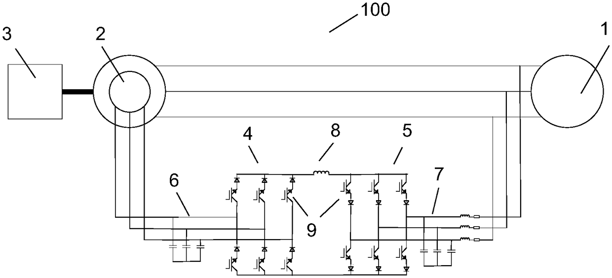
[0047] The invention provides a double-fed motor frequency conversion and speed regulation system based on a current source converter. figure 1 It is a schematic topological structure diagram of a doubly-fed motor frequency conversion speed regulation system 100 based on a current source converter in an embodiment of the present invention.

[0048] Such as figure 1As shown, the doubly-fed machine frequency conversion speed regulation system includes: doubly-fed machine 2 and mechanical load 3 connected with the...

Embodiment 2

[0096] Frequency conversion and speed regulation system of doubly-fed motor based on current source converter

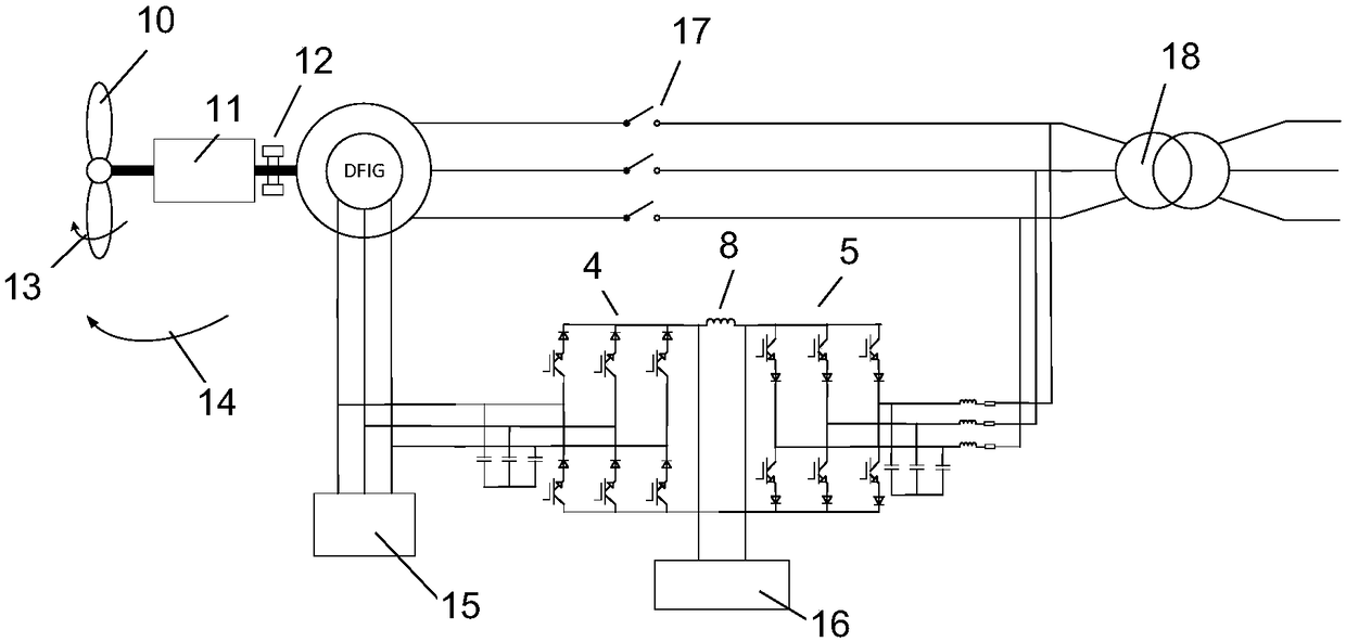
[0097] figure 2 It is the topological structure of the doubly-fed wind power generation system based on the current source converter in an embodiment of the present invention. This topology includes a transformer 18 (connected to a three-phase AC power supply), a double-fed motor and a wind turbine 10 connected to the rotating shaft of the double-fed motor; it also includes: a machine-side converter 4, a grid-side converter 5, a machine side filter 6, grid side filter 7 and DC inductor 8;

[0098] The machine-side converter 4 includes multiple sets of switches connected in parallel, each set of switches includes two series-connected reverse resistance IGBTs and has a collector and an emitter, and each set of switches has a collector constituting the machine-side collector of the machine-side converter, and the emitters of each group of switches constitute the mach...


PUM

PropertyMeasurementUnit
Frequencyaaaaaaaaaa

Abstract

The invention discloses a DC bus current control system of a doubly-fed motor variable-frequency speed regulating system. The DC bus current control system has high steady-state performance, and reduces the DC current of the speed regulating system without changing the power factor of the power grid, so as to increase the service life of the speed regulating system. The DC bus current control system comprises a motor-side converter, a grid-side converter, a motor-side filter, a grid-side filter and a DC inductor. The motor-side filter is connected between the control winding of a doubly-fed motor and the motor-side converter. The grid-side filter is connected between a three-phase AC power supply and the grid-side converter. The motor-side converter and the grid-side converter are connected with each other, and the DC inductor is connected between the motor-side emitter of the motor-side converter and the grid-side collector of the grid-side converter. The power winding of the doubly-fed motor is connected to the three-phase AC power supply. The method includes the following steps: the control winding of the doubly-fed motor provides excitation to reduce the motor-side current andincrease the grid-side current; and a controller makes the motor-side current equal to the grid-side current.

Description

technical field [0001] The invention relates to an asynchronous motor, in particular to a DC bus current control system of a double-fed motor frequency conversion speed regulation system based on a current source converter. Background technique [0002] At present, the converters used in double-fed motor frequency conversion speed regulation systems on the market are mostly thyristor converters or voltage PWM converters, but the circuit topology of this converter has limitations, which are manifested in: It is not easy to realize the parallel connection of multiple converters, so that the total capacity of the converters is limited; the short-circuit protection is not sensitive; and the voltage ride-through capability is not good. The current source converter includes a parallel RB-IGBT switch structure, and the anti-resistance switch RB-IGBT itself has a high switching frequency, so this current source converter has small inductive and capacitive reactance, and can Achieve...

Claims


Application Information

Patent Timeline
IPC IPC(8): H02P27/08
CPCH02P21/22H02P25/02H02P27/085
Inventor 张建文蔡旭李沛元戚宏勋顾越岭韩晓辉
Owner CHINA POWER ENG CONSULTING GRP CORP EAST CHINA ELECTRIC POWER DESIGN INST
Why Eureka
Try Eureka