
Buried optical cable fault ground locator and localization method

A locator and optical cable technology, applied in the field of buried optical cable fault ground locator and localization, can solve the problems of waste of financial and material resources, large workload, low work efficiency, etc., and achieve the effect of accurate positioning and reduction of financial and material resources.

Pending Publication Date: 2019-01-01
昆仑杰信(北京)科技有限责任公司
View PDF0 Cites 16 Cited by
  • Summary
  • Abstract
  • Description
  • Claims
  • Application Information

AI Technical Summary

Problems solved by technology

[0004] However, due to uncontrollable factors such as coil retention, welding, and bending during the laying of optical cables, there is often a large gap between the actual location of the fault point and the length of the optical cable at the fault point measured by the OTDR. OTDR measures the breakpoint distance, uses the measured value to reach a similar location, digs a hole to find the optical cable, and uses OTDR to continue measuring until the cable breakpoint is found. This method is inefficient and requires multiple digging and replacement during the process of finding the breakpoint location, the workload is huge and a lot of financial and material resources are wasted

Method used


Image

  • Buried optical cable fault ground locator and localization method
  • Buried optical cable fault ground locator and localization method

Examples


Embodiment Construction

[0053] The specific embodiments of the present invention will be further described below in conjunction with the accompanying drawings.

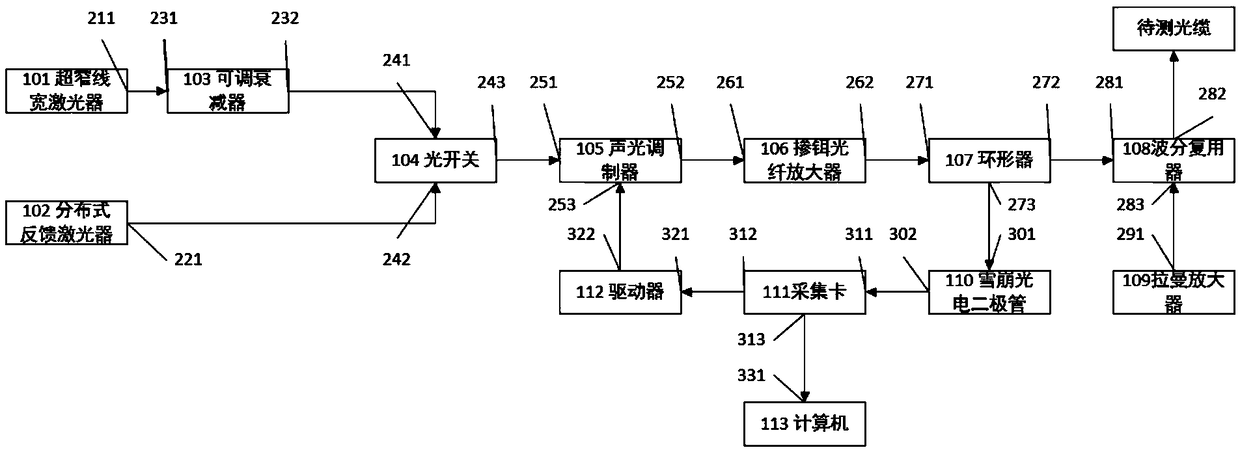
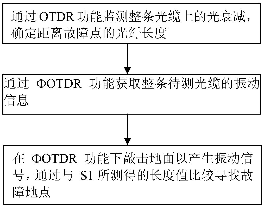
[0054] figure 1 It is a structural composition diagram of a ground locator for buried optical cable failure according to the present invention; figure 2 It is the flow chart of the method for locating the fault point of the buried optical cable according to the present invention.

[0055] Such as figure 1 As shown, the present invention provides a ground locator for buried optical cable faults, including ultra-narrow linewidth laser 101, distributed feedback laser (DFB) 102, adjustable attenuator 103, optical switch 104, acousto-optic modulator 105, doped Erbium fiber amplifier (EDFA) 106, circulator 107, wavelength division multiplexer 108, Raman amplifier 109, avalanche photodiode (APD) 110, capture card 111, driver 112, and computer 113. The output port 211 of the ultra-narrow linewidth laser 101 is connected to the input port 231 of the adj...


PUM


Abstract

The invention belongs to the optical cable fault point localization technical field and relates to a buried optical cable fault ground locator and a localization method. The locator includes an ultra-narrow linewidth laser, a distributed feedback laser, an adjustable attenuator, an optical switch, an acousto-optic modulator, an erbium-doped optical fiber amplifier, a circulator, a wavelength division multiplexer, a Raman amplifier, an avalanche photodiode, an acquisition card, a driver, and a computer. With the buried optical cable fault ground locator and the localization method of the invention adopted, the fault location of a designated optical cable can be accurately located; financial and material resources required in finding the fault location of the optical cable can be effectivelyreduced; and the optical paths of an OTDR and the phiOTDR are fully integrated, the same devices can be adopted to simultaneously realize two functions on the basis of a fact that the devices apply different parameters under different modes.

Description

Technical field [0001] The invention belongs to the technical field of optical cable fault point positioning, and relates to a ground locator for buried optical cable faults and a positioning method. Background technique [0002] With the development of communication technology, optical fiber communication network lines are becoming increasingly complex. In the face of the complex social environment, the workload of fiber optic cable maintenance has been increased. Therefore, faster and more accurate detection of the failure points of buried fiber optic cables has become a demand. [0003] Traditional optical fiber cable fault location and search often use an optical time domain reflectometer (OTDR) to measure the length and location of the fault point. OTDR is an instrument that understands the uniformity, defect, fracture, and coupling of the fiber through the analysis of the measurement curve. It uses the backscattered light generated when light propagates in the fiber to obta...

Claims


Application Information

Patent Timeline
IPC IPC(8): H04B10/071H04B10/077
CPCH04B10/071H04B10/0771
Inventor 曾谷丰倪明陈宇中张学亮向俊贺一珉杨杉
Owner 昆仑杰信(北京)科技有限责任公司
Learn More