A system and method for exhaust water vapor deposition in rail vehicle

A rail vehicle and drainage system technology, applied in the field of rail vehicles, can solve the problems of reducing the thermal insulation capacity of vehicle insulation materials, corrosion of equipment and materials, train riding comfort and the impact of the entire life cycle, to prevent corrosion and ensure heat insulation performance , to avoid the effect of stagnation

Active Publication Date: 2019-01-04
ZHUZHOU ELECTRIC LOCOMOTIVE CO
View PDF6 Cites 2 Cited by
  • Summary
  • Abstract
  • Description
  • Claims
  • Application Information

AI Technical Summary

Problems solved by technology

[0002] With the diversified development of the operating environment of rail cars and the increase of passenger flow, the operating environment span of the vehicle is getting larger and larger, and the heat insulation capacity of the vehicle is getting higher and higher, which also leads to an increasing temperature difference between the inside and outside of the vehicle. Other factors such as water vapor, air humidity, and cleaning fluid will cause a certain amount of condensed water to be generated on the inner wall of the car body profile and the inner wall of the window, and then form water accumulation in the car; if the water vapor in the car is not collected and discharged in time, It will cause serious corrosion of vehicle equipment and materials such as car body profiles, and will also reduce the thermal insulation capacity of vehicle insulation materials, which will affect the ride comfort and life cycle of the train; the existing drainage system in the train only solves the problem of Drainage problems of toilets and air conditioners, no corresponding attention to the problem of water vapor accumulation in the vehicle

Method used


Image

  • A system and method for exhaust water vapor deposition in rail vehicle
  • A system and method for exhaust water vapor deposition in rail vehicle
  • A system and method for exhaust water vapor deposition in rail vehicle

Examples


Embodiment Construction

[0021] The present invention will be further described below by taking a double-deck rail vehicle as an example, but the protection scope of the present invention is not limited thereby.

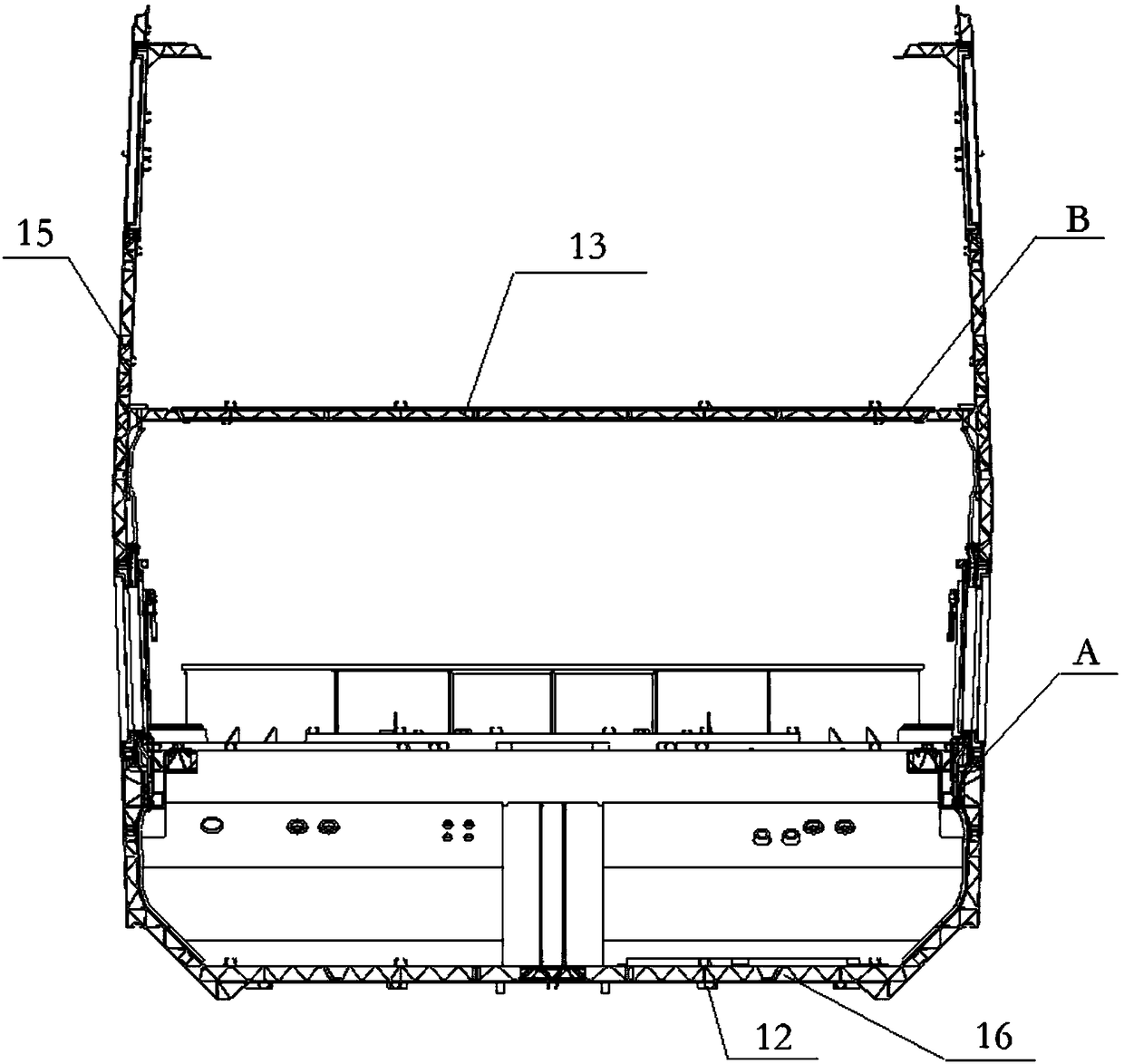
[0022] Such as figure 1 As shown, the water vapor accumulation and drainage system in the rail vehicle of the present invention is composed of two parts, the window accumulation drainage system A and the vehicle volume drainage system B.

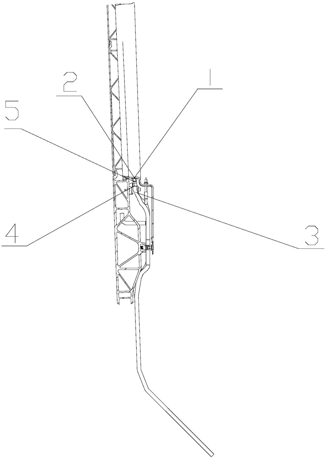
[0023] Such as figure 2 As shown, the vehicle window drainage system is mainly composed of a window sill hidden groove 1, a window sill water storage tank 2, a window drain pipe 3, a window drain pipe joint 4, and a sealant 5; the window sill hidden groove 1 is arranged on the window sill, and the window sill hidden groove 1 is provided with a window sill water storage tank 2, and the bottom of the window sill water storage tank 2 is provided with a window drain pipe joint 4, and the window drain pipe 3 is connected with the vehicle window drain pipe joi...


PUM


Abstract

A system and method for exhaust water vapor deposition in a rail vehicle is disclosed. The system is composed of a window accumulated drainage system and a vehicle body accumulated drainage system, wherein the window drainage system comprises window sill slots (1) arranged on all window sill, the bottom of all window sill slots is provided with a window sill water storage groove (2) communicated with the window sill slot, each window sill water storage tank is sealed and connected with a vehicle window drainage pipe (3), the lower end of each vehicle window drainage pipe is connected with a stagnant water tank arranged on a vehicle body floor (13), or is directly connected with an air-tight drainage tank (12) arranged on a vehicle body chassis. The vehicle body accumulated drainage systemcomprises a plurality of drainage guides (6) arranged on the vehicle body floor and communicating vertically and horizontally. Both sides of the vehicle body floor form the sump receiving the drainageguide bar conveying water through the body profile and the drainage block (9) and the drainage guide bar, and the sump is sealedly connected to the drainage hose (8), the lower end of the drainage hose is connected to the airtight drain groove provided on the chassis of the vehicle body.

Description

technical field [0001] The invention relates to a rail vehicle, in particular to a water vapor accumulating and discharging system and method in the rail vehicle. Background technique [0002] With the diversified development of the operating environment of rail cars and the increase of passenger flow, the operating environment span of the vehicle is getting larger and larger, and the heat insulation capacity of the vehicle is getting higher and higher, which also leads to an increasing temperature difference between the inside and outside of the vehicle. Other factors such as water vapor, air humidity, and cleaning fluid will cause a certain amount of condensed water to be generated on the inner wall of the car body profile and the inner wall of the window, and then form water accumulation in the car; if the water vapor in the car is not collected and discharged in time, It will cause serious corrosion of vehicle equipment and materials such as car body profiles, and will a...

Claims


Application Information

Patent Timeline
IPC IPC(8): B61D49/00B61D25/00B61D17/00
CPCB61D17/00B61D25/00B61D49/00
Inventor 刘强谢红兵周安德李坤
Owner ZHUZHOU ELECTRIC LOCOMOTIVE CO
Why Eureka
Try Eureka