Spiral-flow type reflux hydrolytic acidification reactor

An acidification reactor and reactor technology, applied in the direction of water distribution pipes, anaerobic digestion treatment, etc., can solve the problems of low operating efficiency, muddy water, insufficient mixing of muddy water, etc., and achieve the effect of improving reaction efficiency

Active Publication Date: 2019-01-04
SUZHOU KEDA ENVIRONMENTAL PROTECTION ENG CO LTD
View PDF6 Cites 0 Cited by
  • Summary
  • Abstract
  • Description
  • Claims
  • Application Information

AI Technical Summary

Problems solved by technology

[0002] Hydrolytic acidification is the first part of the anaerobic reaction, which mainly uses anaerobic and concurrently trophic microorganisms to decompose macromolecular substances in wastewater, and the existing hydrolytic acidification reactors are mainly divided into packed type and upflow type hydrolysis acidification reactors , but in the process of actual operation, the existence of these two hydrolytic acidification reactors has low operating efficiency, insufficient mixing of mud and water, and muddy water

Method used


Image

  • Spiral-flow type reflux hydrolytic acidification reactor
  • Spiral-flow type reflux hydrolytic acidification reactor
  • Spiral-flow type reflux hydrolytic acidification reactor

Examples


Embodiment 1

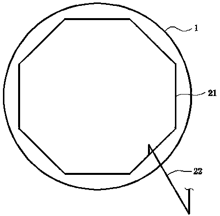
[0030] refer to Figure 1-5 , a swirl type reflux hydrolysis acidification reactor, comprising a reactor body 1, the top of the reactor body 1 is connected with an outlet weir 2, the outlet weir 2 is connected with an outlet pipe 3, and the upper end of the reactor body 1 is internally connected with a retaining ring 4 , the bottom of the reactor body 1 is arranged with a mud discharge pipe 21, the mud discharge pipe 21 is connected with a mud discharge pipe 22, and a PE baffle assembly 5 is arranged inside the upper end of the reactor body 1, and the PE baffle assembly 5 is located in the retaining ring 4, the bottom of the reactor body 1 is provided with a first PE water distribution pipe 18 and a second PE water distribution pipe 17, and the first PE water distribution pipe 18 and the second PE water distribution pipe 17 are respectively connected with a first water spray head 20 and a second PE water distribution pipe 17. Water spray head 19; through the first PE water dis...

Embodiment 2

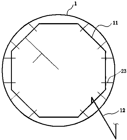
[0032] refer to Figure 1-8, a swirl type reflux hydrolysis acidification reactor, which is basically the same as in Example 1, the difference is that the first PE water distribution pipe 18 and the second PE water distribution pipe 17 are connected with the first water inlet pipe 16 and the second water inlet pipe 17 respectively. The water pipe 15, the upper end of the reactor body 1 is arranged with a return water distribution perforated pipe 11, the return water distribution perforated pipe 11 is connected with the second water inlet pipe 15 through the return pipe 12, the return pipe 12 is connected with a pressurized water pump 13, the first PE cloth The water pipe 18 and the second PE water distribution pipe 17 are respectively connected with the first water inlet pipe 16 and the second water inlet pipe 15, and the upper end of the reactor body 1 is arranged with a return water distribution perforated pipe 11, and the return water distribution perforated pipe 11 passes t...

Embodiment 3

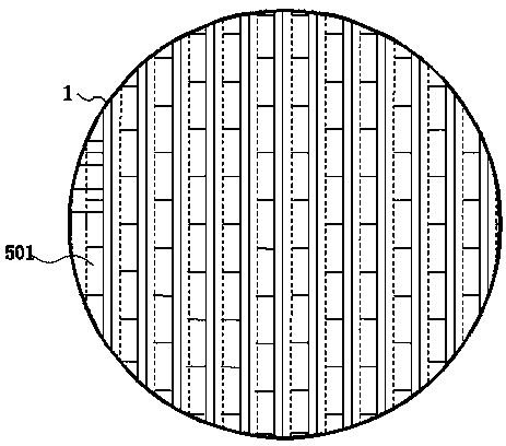
[0035] refer to Figure 4-5 , a swirl type reflux hydrolysis acidification reactor, which is basically the same as Example 1, the difference is that the PE baffle assembly 5 includes an angle iron 501, a folded plate 504, a fixed support rod 502, and the folded plate 504 is fixedly connected to On the angle iron 501, the folded plate 504 is fixedly connected to the angle iron 501 through the fixed support rod 502, and the angle iron 501 is fixedly connected with a support seat 503, and the upper end of the support seat 503 is offset against the bottom side of the bend of the fold plate 504, and the angle iron 501 facilitates the stable connection of the flap 504 to the reactor body 1. When the three-item mixture of mud, water and air enters the PE baffle assembly 5, the flap 504 is used to block the water, and the water collects on the top of the flap 504, and the mud and Water enters the outside of the folded plate 504 and moves upward, where it is blocked by the folded plate...


PUM


Abstract

The invention discloses a spiral-flow type reflux hydrolytic acidification reactor and belongs to the field of sewage treatment reactors. The spiral-flow type reflux hydrolytic acidification reactor comprises a reactor body and is characterized in that an effluent weir is connected to the top of the reactor body, a water outlet pipe is connected to the effluent weir, a retaining ring is connectedinto the upper end of the reactor body, a sludge discharge pipe is arranged at the bottom of the reactor body, a sludge outlet pipe is connected to the sludge discharge pipe, a PE baffle plate component is further arranged inside the upper end of the reactor body, the PE baffle plate component is located above the retaining ring, and a first PE water distribution pipe and a second water distribution pipe are arranged at the bottom of the reactor body. The spiral-flow type reflux hydrolytic acidification reactor has the advantages that sewage is sufficiently mixed with sludge in the reactor body, rotation-ascending spiral flow is formed, reaction efficiency is increased, sludge concentration in the reactor is guaranteed, the sewage is separated from treated sewage, and the sludge is retained in the efficient hydrolytic acidification reactor.

Description

technical field [0001] The invention relates to the technical field of sewage treatment reactors, in particular to a cyclone type reflux hydrolysis acidification reactor. Background technique [0002] Hydrolytic acidification is the first part of the anaerobic reaction, mainly using anaerobic and concurrently trophic microorganisms to decompose macromolecular substances in wastewater, and the existing hydrolytic acidification reactors are mainly divided into packed type and upflow type hydrolysis acidification reactors , but in the process of actual operation, the existence of these two hydrolytic acidification reactors has low operating efficiency, insufficient mixing of mud and water, and muddy water. [0003] Therefore, there is an urgent need to develop a method that can not only ensure that the sewage in the reactor is fully mixed with the sludge in the reactor, thereby improving the removal efficiency of microorganisms on pollutants in the sewage, but also ensuring the...

Claims


Application Information

Patent Timeline
Patent Type & Authority Applications(China)
IPC IPC(8): C02F3/28
CPCC02F1/006C02F3/28
Inventor 王学华王浩
Owner SUZHOU KEDA ENVIRONMENTAL PROTECTION ENG CO LTD
Why Eureka
Try Eureka