Cloth block color spraying equipment used for textile dyeing

A textile and cloth block technology, applied in the field of cloth block color spraying equipment for textile dyeing, can solve the problems of dye precipitation, uneven dyeing of cloth blocks, etc., achieve the effect of uniformity and increase the stirring area

Active Publication Date: 2019-01-04
绍兴柯桥瑞策纺织有限公司
View PDF7 Cites 5 Cited by
  • Summary
  • Abstract
  • Description
  • Claims
  • Application Information

AI Technical Summary

Problems solved by technology

[0003] In order to overcome the current disadvantages of dye precipitation due to lack of stirring of the dye and uneven dyeing on the upper and lower sides of the cloth when dyeing the cloth, the technical problem to be solved is: to provide a dye that is not stirred to cause the dye to Cloth color spraying equipment for textile dyeing with sedimentation and uniform dyeing on the upper and lower sides of the cloth

Method used


Image

  • Cloth block color spraying equipment used for textile dyeing
  • Cloth block color spraying equipment used for textile dyeing
  • Cloth block color spraying equipment used for textile dyeing

Examples


Embodiment 1

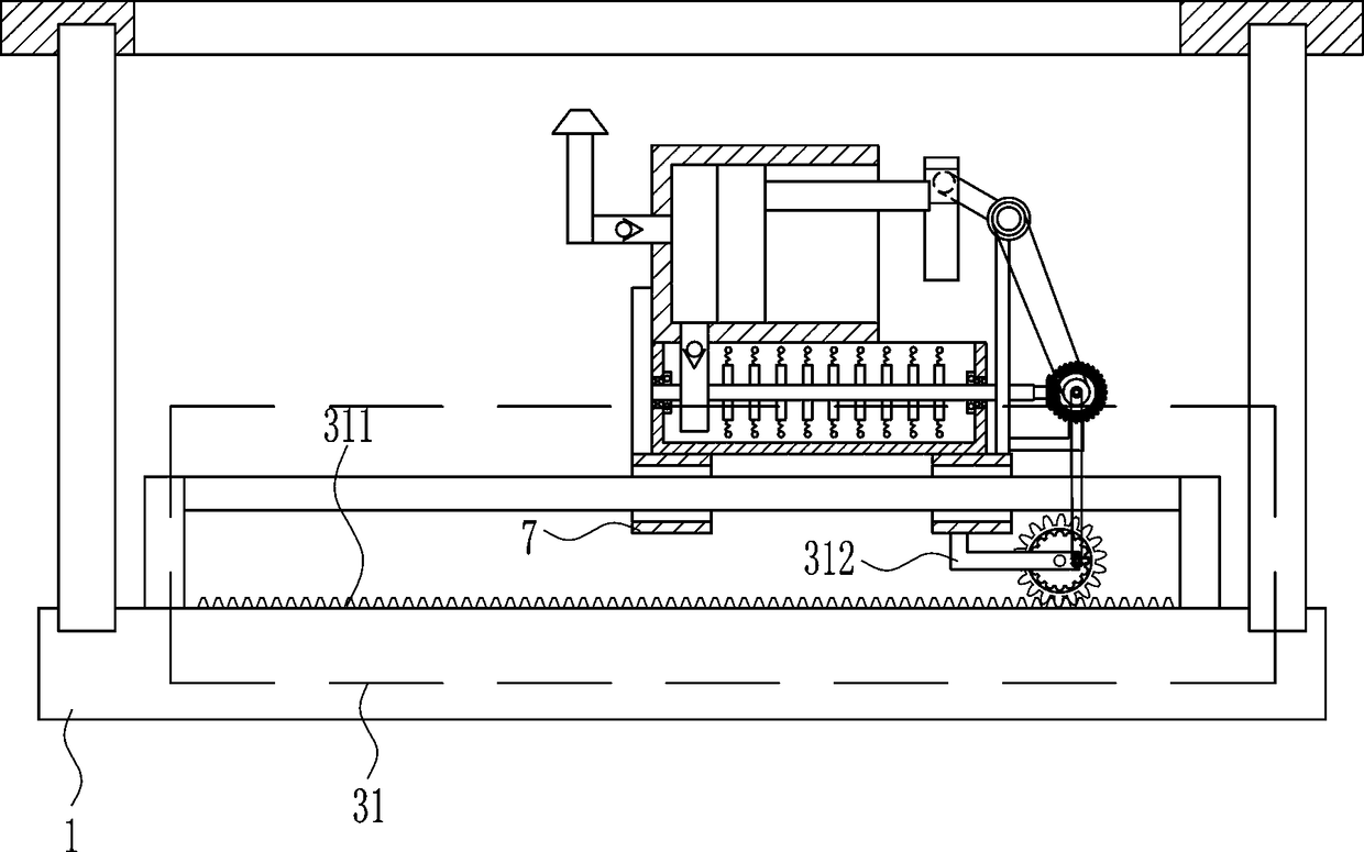
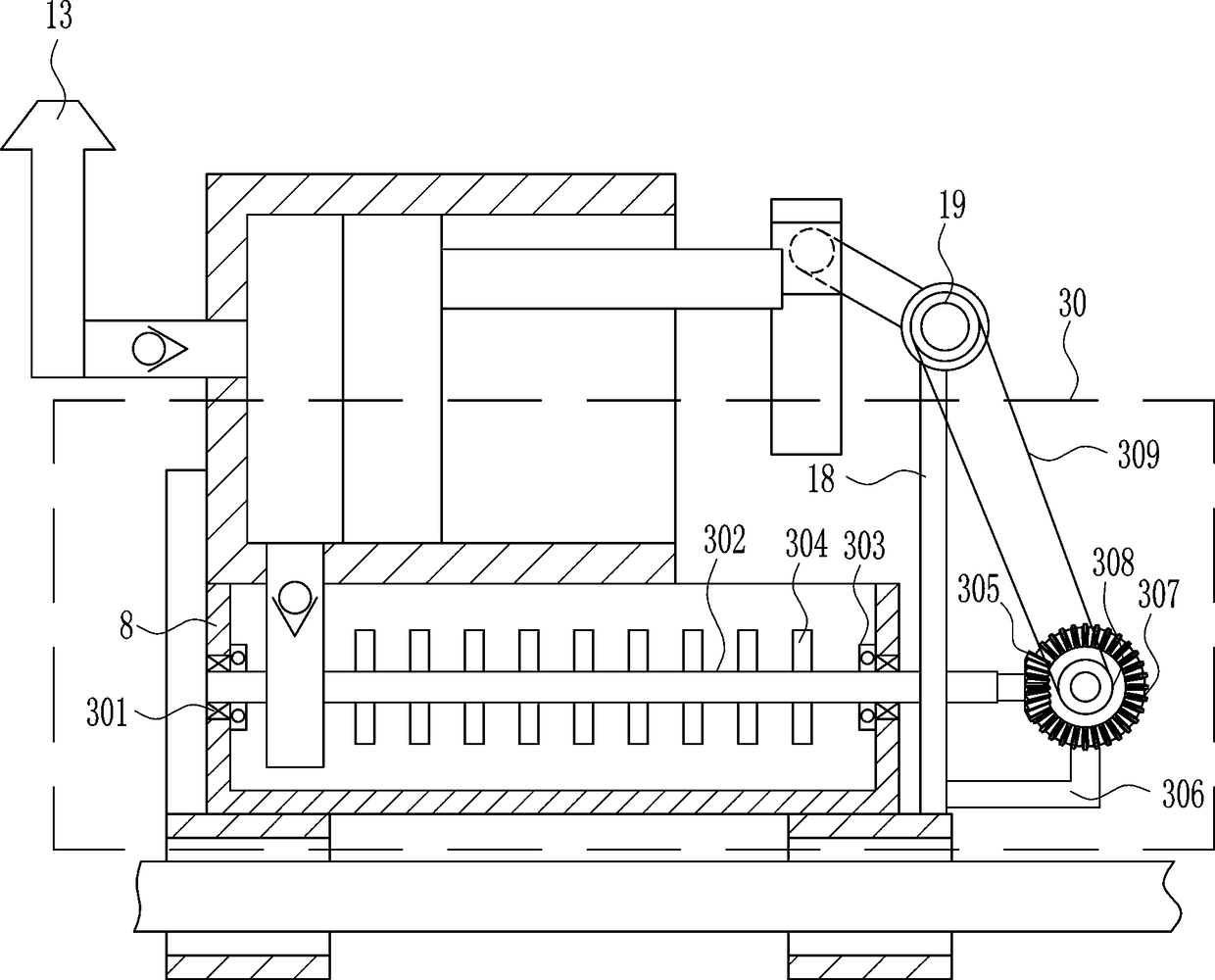
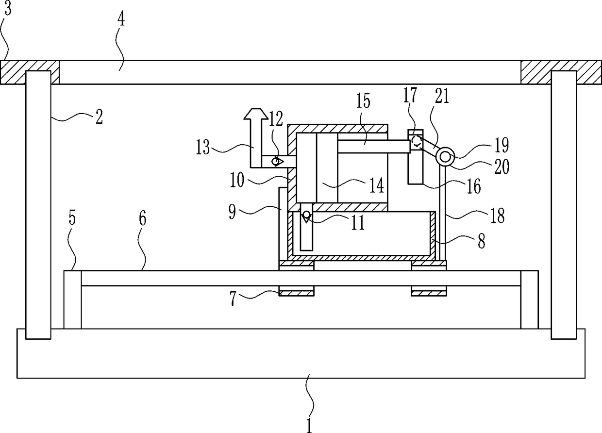
[0024] A cloth color spraying equipment for textile dyeing, such as Figure 1-6 As shown, it includes a bottom plate 1, a support rod 2, a placement plate 3, a bracket 5, a guide rail 6, a guide sleeve 7, a dye box 8, a connecting rod 9, a piston cylinder 10, a first one-way valve 11, a second one-way valve 12. Nozzle 13, piston block 14, push rod 15, slide rail 16, slider 17, fixed rod 18, electric wheel 19, turntable 20 and rocker 21, the bottom plate 1 is connected with support rods 2 on the front, rear, left, and right sides , a placement plate 3 is connected between the upper sides of the support rods 2, a rectangular hole 4 is opened in the middle of the placement plate 3, brackets 5 are connected to the left and right sides of the upper side of the bottom plate 1, and guide rails 6 are connected between the upper inner sides of the brackets 5, and the guide rails 6 There are two guide sleeves 7 connected in the upper slide type, a dye box 8 is connected between the uppe...

Embodiment 2

[0026] A cloth color spraying equipment for textile dyeing, such as Figure 1-6As shown, it includes a bottom plate 1, a support rod 2, a placement plate 3, a bracket 5, a guide rail 6, a guide sleeve 7, a dye box 8, a connecting rod 9, a piston cylinder 10, a first one-way valve 11, a second one-way valve 12. Nozzle 13, piston block 14, push rod 15, slide rail 16, slider 17, fixed rod 18, electric wheel 19, turntable 20 and rocker 21, the bottom plate 1 is connected with support rods 2 on the front, rear, left, and right sides , a placement plate 3 is connected between the upper sides of the support rods 2, a rectangular hole 4 is opened in the middle of the placement plate 3, brackets 5 are connected to the left and right sides of the upper side of the bottom plate 1, and guide rails 6 are connected between the upper inner sides of the brackets 5, and the guide rails 6 There are two guide sleeves 7 connected in the upper slide type, a dye box 8 is connected between the upper...

Embodiment 3

[0029] A cloth color spraying equipment for textile dyeing, such as Figure 1-6 As shown, it includes a bottom plate 1, a support rod 2, a placement plate 3, a bracket 5, a guide rail 6, a guide sleeve 7, a dye box 8, a connecting rod 9, a piston cylinder 10, a first one-way valve 11, a second one-way valve 12. Nozzle 13, piston block 14, push rod 15, slide rail 16, slider 17, fixed rod 18, electric wheel 19, turntable 20 and rocker 21, the bottom plate 1 is connected with support rods 2 on the front, rear, left, and right sides , a placement plate 3 is connected between the upper sides of the support rods 2, a rectangular hole 4 is opened in the middle of the placement plate 3, brackets 5 are connected to the left and right sides of the upper side of the bottom plate 1, and guide rails 6 are connected between the upper inner sides of the brackets 5, and the guide rails 6 There are two guide sleeves 7 connected in the upper slide type, a dye box 8 is connected between the uppe...


PUM


Abstract

The invention relates to textile dyeing equipment and especially relates to cloth block color spraying equipment used for textile dyeing. By using the cloth block color spraying equipment used for thetextile dyeing provided in the invention, dye is not stirred so that the dye generates sediments, and the dyeing of the upper and lower sides of a cloth block is uniform. The cloth block color spraying equipment used for the textile dyeing comprises a base plate, support rods, a placing plate, supports, a guide rail, a guide sleeve, a dye box, a connection rod and the like. The left and right portions of the front and rear sides of the base plate are connected to the support rods. The placing plate is connected between the upper sides of the support rods. The central section of the placing plate is provided with a rectangular hole. The left and right sides of the upper side of the base plate are connected to supports. In the invention, through an agitating blade, the dye in the dye box isstirred and is prevented from generating the sediments; the agitating blade drives a spring and a centrifugal ball to carry out centrifugal motion so as to increase a stirring area; and through a mode that a spray nozzle automatically moves and sprays color to the cloth block, the sprayed color of the upper and lower sides of the cloth block can be consistent, which means that the uniformity of the dye is consistent.

Description

technical field [0001] The invention relates to a textile dyeing device, in particular to a cloth block color spraying device for textile dyeing. Background technique [0002] Cloth is a kind of textile. When the cloth is just made, it is white. Before it is put into use or sold, it needs to be dyed to make the cloth less monotonous and more beautiful. Currently, the cloth is dyed Most of the time, the cloth is directly dyed in the dyeing vat, but the dye in the dyeing vat may precipitate, which will lead to uneven dyeing of the cloth, and during the dyeing process, because the dyeing vat The appearance of precipitation will lead to different color levels in the dyeing vat, which will also affect the uniformity of cloth dyeing. Contents of the invention [0003] In order to overcome the current disadvantages of dye precipitation due to lack of stirring of the dye and uneven dyeing on the upper and lower sides of the cloth when dyeing the cloth, the technical problem to be...

Claims


Application Information

Patent Timeline
Patent Type & Authority Applications(China)
IPC IPC(8): D06B1/02D06B23/20
CPCD06B1/02D06B23/20D06B23/205
Inventor 傅云峰
Owner 绍兴柯桥瑞策纺织有限公司
Why Eureka
Try Eureka