Hydrogen-mixed working medium power-generation system
A technology of power generation system and mixed working fluid, applied in the field of hydrogen mixed working fluid power generation system, can solve the problems of low energy conversion rate of the system, low power generation of the generator, limited promotion value, etc., achieve the economic benefits of energy saving and emission reduction, and create Economic benefits, the effect of increasing the economic benefits of enterprises
- Summary
- Abstract
- Description
- Claims
- Application Information
AI Technical Summary
Problems solved by technology
Method used
Image
Examples
Embodiment 1
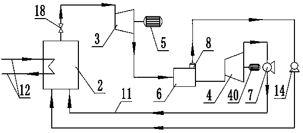
[0022] Hydrogen mixed working medium power generation system of the present invention such as figure 1 As shown, it includes a mixed gasifier 2 , a mixed gas expander 3 , a liquid-laden expander 4 , a generator 5 , a gas separator 6 , an air heat exchange pipeline 12 , a hydrogen pressurizer 14 and a liquid pressurizer pump 7 . The gas mixture expander is connected to the shaft of the generator, and the electricity generated by the generator is connected to the grid. The air heat exchange pipeline 12 is connected to the tube side inlet of the mixed gasifier 2 , and the tube side outlet of the air heat exchange pipeline 12 is communicated with the atmosphere. The mixed gasifier 2 is provided with a hydrogen inlet, a condensate inlet and a mixed gas outlet, the gas separator 6 is provided with a hydrogen outlet, a nitrogen outlet and a mixed gas inlet, and the hydrogen outlet is provided with a hydrogen filter membrane 8 . The outlet of the mixed gas expander is connected to th...
Embodiment 2
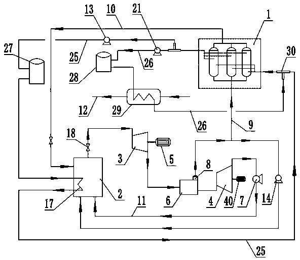
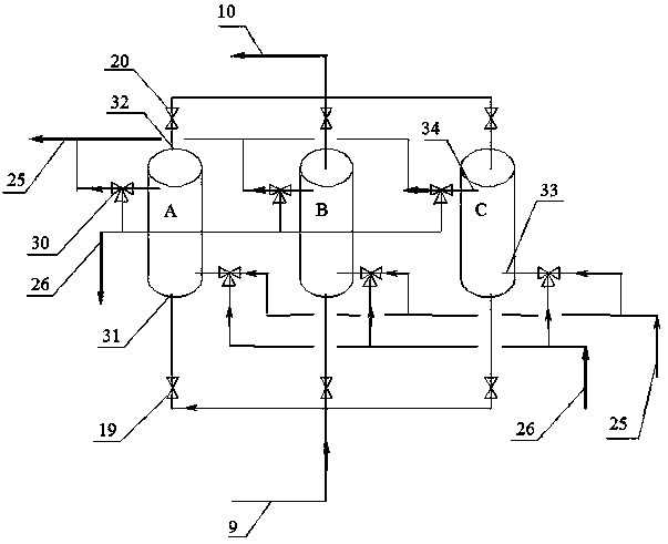
[0026] Another embodiment of the present invention is as figure 2 As shown, it includes hydrogen reaction bed unit 1, mixed gasifier 2, mixed gas expander 3, liquid-laden expander 4, generator 5, gas separator 6, hydrogen pressurizer 14, air heat exchange pipeline 12, Cooling hydrogen pipeline 25, heating hydrogen pipeline 26, No. 1 hydrogen intermediate tank 27, No. 2 hydrogen intermediate tank 28, air heat exchanger 29, heat exchange medium high pressure hydrogen circulation pump 21, heat exchange medium low pressure hydrogen circulation pump 13 and Liquid booster pump7. The gas-mixed expander 3 and the liquid-filled expander 4 are respectively connected to the generator 5 and No. 2 generator 40 shafts, and the electricity generated by the generator is used for self-use, and the rest is incorporated into the grid for external supply. like image 3 As shown, the hydrogen reaction bed unit 1 is provided with three hydrogen reaction beds, No. 1 hydrogen reaction bed A, No. 2...
Embodiment 3
[0038] The third embodiment of the present invention is as Figure 4 As shown, it includes hydrogen reaction bed unit 1, mixed gasifier 2, mixed gas expander 3, liquid-laden expander 4, generator 5, gas separator 6, hydrogen pressurizer 14, air heat exchange pipeline 12, Cooling hydrogen pipeline 25, heating hydrogen pipeline 26, No. 1 hydrogen intermediate tank 27, No. 2 hydrogen intermediate tank 28, air heat exchanger 29, heat exchange medium high pressure hydrogen circulation pump 21, heat exchange medium low pressure hydrogen circulation pump 13 and Liquid booster pump7. Mixed gas expander 3, liquid-carrying expander 4, and pure hydrogen expander 44 are respectively connected to generator 5, No. 2 generator 40, and No. 3 generator 43. Part of the electricity generated by the generator is for self-use, and the rest is incorporated into the grid. for. like image 3 As shown, the hydrogen reaction bed unit 1 is provided with three hydrogen reaction beds, No. 1 hydrogen re...
PUM
 Abstract
Description
Claims
Application Information
 - R&D
- Intellectual Property
- Life Sciences
- Materials
- Tech Scout
- Unparalleled Data Quality
- Higher Quality Content
- 60% Fewer Hallucinations
Browse by: Latest US Patents, China's latest patents, Technical Efficacy Thesaurus, Application Domain, Technology Topic, Popular Technical Reports.
© 2025 PatSnap. All rights reserved.Legal|Privacy policy|Modern Slavery Act Transparency Statement|Sitemap|About US| Contact US: help@patsnap.com


