Hydrogen heat exchange medium monometal hydride acting system

A technology of heat exchange medium and hydride, which is applied in the direction of steam engine devices, machines/engines, mechanical equipment, etc., can solve problems affecting safe use, knocking, instability, etc., achieve economic benefits of energy saving and emission reduction, and create economic benefits Effect

Pending Publication Date: 2020-04-10
SHANGHAI KELAIPU ENERGY TECH CO LTD
View PDF0 Cites 0 Cited by
  • Summary
  • Abstract
  • Description
  • Claims
  • Application Information

AI Technical Summary

Problems solved by technology

Traditional hydrogen energy utilization mostly obtains thermal energy and kinetic energy by directly burning gaseous hydrogen, but gaseous hydrogen is not easy to store and transport, and the hydrogen energy obtained from combustion is directly used in the power system, which will cause a series of problems that affect safe use, such as knocking and instability.

Method used


Image

  • Hydrogen heat exchange medium monometal hydride acting system
  • Hydrogen heat exchange medium monometal hydride acting system
  • Hydrogen heat exchange medium monometal hydride acting system

Examples


Embodiment 1

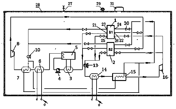
[0017] The hydrogen heat exchange medium single metal hydride work system of the present invention is as follows figure 1 As shown, it includes B1 metal hydrogen storage reaction bed 1, B2 metal hydrogen storage reaction bed 2, hydrogen liquefier 3, A air heat exchanger 6, A hydrogen heat exchanger 7, liquid hydrogen high pressure pump 4, high pressure hydrogen circulation pump 10 , B air heat exchanger 14, liquid nitrogen high pressure pump 13, nitrogen expander 16, B hydrogen heat exchanger 15 and refrigeration unit 5. The B1 metal hydrogen storage reaction bed 1 and the B2 metal hydrogen storage reaction bed 2 are respectively provided with a hydrogen absorption inlet 22 , a hydrogen discharge outlet 21 , a heat exchange inlet 24 , a heat exchange outlet 23 , a liquid nitrogen outlet 25 and a nitrogen gas inlet 26 . The hydrogen discharge outlet 21 of B1 metal hydrogen storage reaction bed 1 and B2 metal hydrogen storage reaction bed 2 is connected to the liquid hydrogen hi...

Embodiment 2

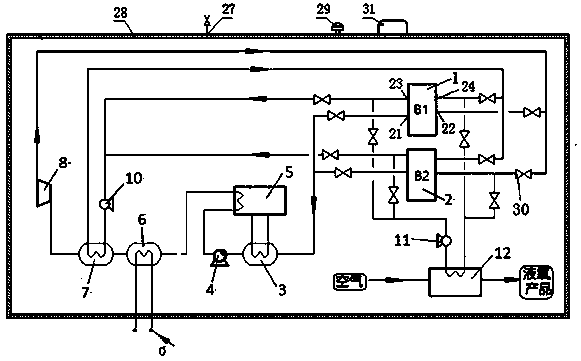
[0024] Another embodiment of the present invention is as figure 2 As shown, it includes B1 metal hydrogen storage reaction bed 1, B2 metal hydrogen storage reaction bed 2, hydrogen liquefier 3, A air heat exchanger 6, A hydrogen heat exchanger 7, hydrogen expander 8, liquid hydrogen high pressure pump 4, A high-pressure hydrogen circulation pump 10 , a low-pressure hydrogen circulation pump 11 , a liquid oxygen production unit 12 and a refrigeration unit 5 . The B1 metal hydrogen storage reaction bed 1 and the B2 metal hydrogen storage reaction bed 2 are respectively provided with a hydrogen absorption inlet 22 , a hydrogen discharge outlet 21 , a heat exchange inlet 24 and a heat exchange outlet 23 . The hydrogen discharge outlet 21 of B1 metal hydrogen storage reaction bed 1 and B2 metal hydrogen storage reaction bed 2 is connected to the liquid hydrogen high-pressure pump 4 through the hydrogen liquefier 3 through the high-pressure hydrogen pipeline, and the outlet of the ...


PUM


Abstract

The invention relates to a hydrogen heat exchange medium monometal hydride acting system, and the system comprises a B1 metal hydrogen storage reaction bed, a B2 metal hydrogen storage reaction bed, ahydrogen expansion machine, an A air heat exchanger, an A hydrogen heat exchanger and a refrigerating unit. Hydrogen release outlets of the B1 metal hydrogen storage reaction bed and the B2 metal hydrogen storage reaction bed are connected to hydrogen absorption inlets of the B2 metal hydrogen storage reaction bed and the B1 metal hydrogen storage reaction bed through a hydrogen liquefier, a liquid hydrogen high-pressure pump, a refrigeration unit, an air heat exchanger A, a hydrogen heat exchanger A and a hydrogen expander; heat exchange outlets of the B1 metal hydrogen storage reaction bedand the B2 metal hydrogen storage reaction bed are connected to heat exchange inlets of the B1 metal hydrogen storage reaction bed and the B2 metal hydrogen storage reaction bed through a high-pressure hydrogen circulating pump and a heat exchange tube pass of the A hydrogen heat exchanger. The hydrogen absorption / desorption characteristics of the metal hydride are utilized, the expansion machineacts to drive acting equipment or a generator to generate electricity, natural energy and industrial waste heat are fully utilized, energy conservation and emission reduction are facilitated, and economic benefits are created.

Description

technical field [0001] The invention belongs to the technical field of energy comprehensive utilization, and relates to a hydrogen heat exchange medium single metal hydride work system. Background technique [0002] Energy shortage, environmental pollution, and global climate change make it urgent to develop clean, efficient, safe and sustainable energy, among which hydrogen energy is being valued by more and more countries. In the 21st century, the engine industry has developed rapidly, but gasoline engines and diesel engines are still the main choices of engines. Gasoline and diesel are non-renewable resources. In order to alleviate a series of negative effects brought about by the shortage of petroleum resources, as well as reduce air pollution and engine exhaust emissions, it is necessary to find alternative fuels for engines, and hydrogen energy is currently the most ideal clean fuel. . With the increasingly stringent environmental protection measures around the world...

Claims


Application Information

Patent Timeline
IPC IPC(8): F01K25/08F01K27/00
CPCF01K25/08F01K27/00
Inventor 贾鹏
Owner SHANGHAI KELAIPU ENERGY TECH CO LTD
Why Eureka
Try Eureka