Self-cleaning chimney

A self-cleaning, chimney technology, applied in the direction of combustion product treatment, combustion method, solid residue removal, etc., can solve the problem of lack of cleaning mechanism in the chimney, achieve the effect of reducing maintenance frequency, outstanding effect, and increasing the circulation area

Inactive Publication Date: 2019-01-04
张志华
View PDF5 Cites 6 Cited by
  • Summary
  • Abstract
  • Description
  • Claims
  • Application Information

AI Technical Summary

Problems solved by technology

[0004] The purpose of the present invention is to solve the problem that chimneys in the prior art lack effective cleaning mechanisms, and propose a self-cleaning chimney

Method used


Image

  • Self-cleaning chimney
  • Self-cleaning chimney
  • Self-cleaning chimney

Examples


Embodiment 1

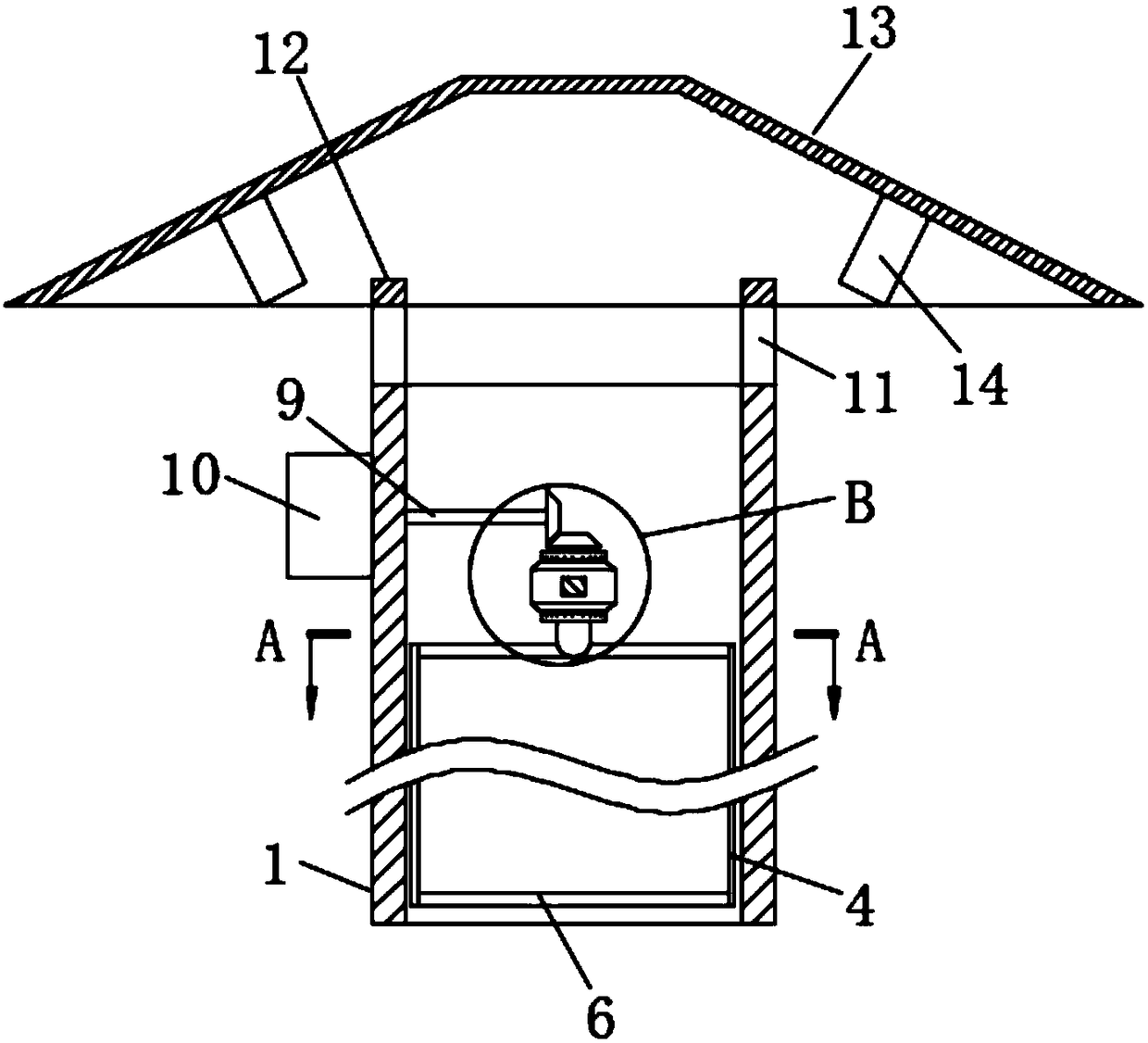
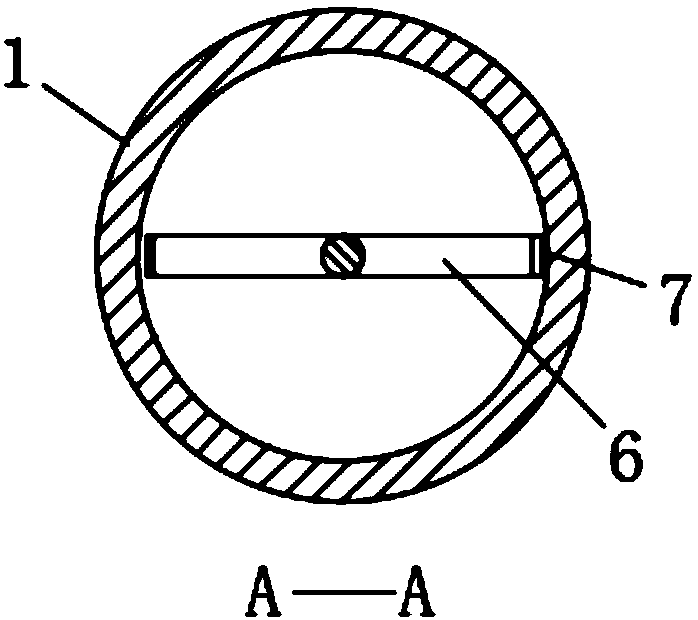
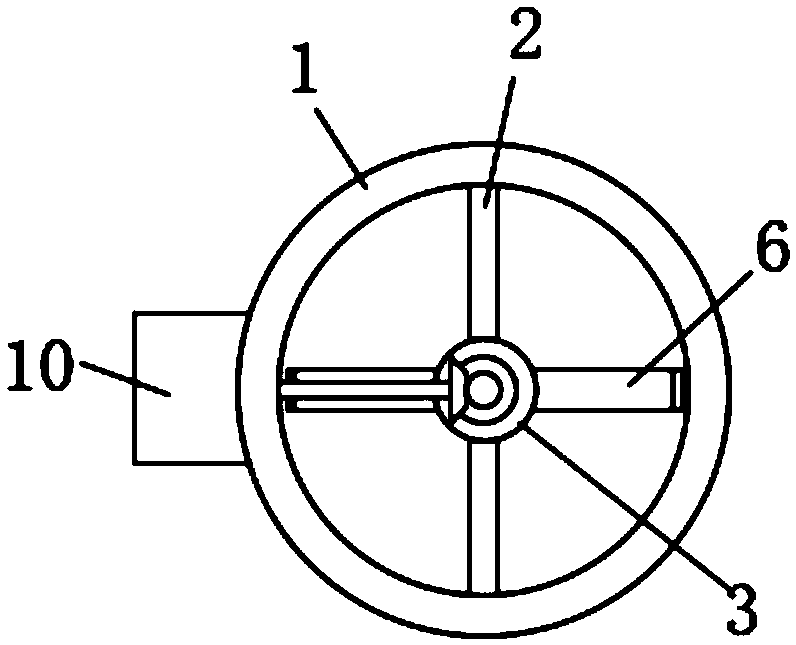
[0030] refer to Figure 1-5 , a self-cleaning chimney, including a chimney 1, two mounting rods 2 are symmetrically fixedly connected to the inner wall of the chimney 1, and a fixing seat 3 is installed between the two mounting rods 2, and the top and bottom ends of the fixing seat 3 are both A bevel of 45 degrees is set upside down, and a bevel is set on the fixing seat 3 so that the smoke can flow upward more smoothly without being blocked by the bottom surface of the fixing seat 3. A rotating rod 5 is vertically inserted on the fixing seat 3, And the rotating rod 5 is set through the fixed seat 3, and the bottom end of the rotating rod 5 is horizontally equipped with a wing plate 6, and the two ends of the wing plate 6 are connected with a stainless steel scraper 4, and the stainless steel scraper 4 is connected to the inner side wall of the chimney 1. The distance is L: 5mm≤L≤10mm, and the thickness of the stainless steel scraper 4 is S: 0.2mm≤S≤0.5mm. When the rotating ro...

Embodiment 2

[0037] refer to Image 6 , a self-cleaning chimney, including a chimney 1, two mounting rods 2 are symmetrically fixedly connected to the inner wall of the chimney 1, and a fixing seat 3 is installed between the two mounting rods 2, and the top and bottom ends of the fixing seat 3 are both An inclination angle of 45 degrees is provided upside down, and a rotating rod 5 is inserted vertically on the fixing seat 3, and the rotating rod 5 is arranged through the fixing seat 3, and the bottom end of the rotating rod 5 is horizontally equipped with a wing plate 6, and the two sides of the wing plate 6 Both ends are connected with a stainless steel scraper 4, and the bottom ends of the two stainless steel scrapers 4 are also connected with a wing plate 6.

[0038] The difference from Embodiment 1 is that the stainless steel scraper 4 is in contact with the inner wall of the chimney 1, and the thickness of the stainless steel scraper 4 is S: 0.5mm≤S≤1mm. When the rotating rod 5 rotat...


PUM


Abstract

The invention discloses a self-cleaning chimney. The self-cleaning chimney comprises a chimney body; two mounting rods are symmetrically and fixedly connected to the inner side wall of the chimney body, a fixing seat is mounted between the two mounting rods, a rotating rod is vertically inserted on the fixing seat, and the rotating rod penetrates through the fixing seat; a wing plate is horizontally mounted at the bottom end of the rotating rod, the two ends of the wing plate are connected with stainless steel scraping sheets correspondingly, and the bottom ends of the two stainless steel scraping sheets are connected with the wing plate as well; and a first bevel gear is mounted at the top end of the rotating rod, a driving motor is mounted on the outer side wall of the chimney body, anda connecting rod is mounted on a motor shaft of the driving motor through a coupling. According to the self-cleaning chimney, a driving mechanism is transferred to the exterior of the chimney, a scraping brush mechanism is arranged to clear the inner wall of the chimney body, meanwhile, the wing plate is utilized to assist smoke in being upwards discharged, the circulating area of the interior ofthe chimney is increased, meanwhile, power during smoke discharging is improved, flue gas is promoted to be discharged more quickly, and the discharging efficiency is greatly improved.

Description

technical field [0001] The invention relates to the technical field of chimney cleaning, in particular to a self-cleaning chimney. Background technique [0002] A chimney is a structure that provides ventilation for the hot flue gases or fumes of a boiler, furnace, furnace or fireplace, the chimney is usually vertical, or as close to vertical as possible, to ensure a smooth flow of gases, sucking air into the so-called chimney combustion or chimney effect, the space inside the chimney is called the flue. [0003] Chimneys are relatively common in industrial production. We often see smokey chimneys in industrial areas. After long-term use of chimneys, a large amount of smoke will accumulate in the flue, and these smoke will gradually clog the inner wall of the flue. The flue gas makes the flue gas flow rate smaller and affects the normal emission of flue gas. Some devices for cleaning the flue have appeared in the prior art, and these devices generally install the entire st...

Claims


Application Information

Patent Timeline
Patent Type & Authority Applications(China)
IPC IPC(8): F23J11/00F23J13/08F23J3/02
CPCF23J11/00F23J3/026F23J13/08
Inventor 张志华
Owner 张志华
Why Eureka
Try Eureka