Check patentability & draft patents in minutes with Patsnap Eureka AI!

Distributed optical fiber sensor

A distributed optical fiber and sensor technology, applied in the direction of converting sensor output, using optical devices to transmit sensing components, instruments, etc., to achieve the effect of improving measurement accuracy

Active Publication Date: 2019-01-04
STATE GRID HEBEI ELECTRIC POWER RES INST +2
View PDF7 Cites 1 Cited by
  • Summary
  • Abstract
  • Description
  • Claims
  • Application Information

AI Technical Summary

Problems solved by technology

At present, there are few reports on the detection of transformer winding temperature and strain based on distributed optical fiber sensing technology.

Method used


Image

  • Distributed optical fiber sensor
  • Distributed optical fiber sensor
  • Distributed optical fiber sensor

Examples


Embodiment Construction

[0059] The standard parts used in the present invention can be purchased from the market, and the special-shaped parts can be customized according to the instructions and the accompanying drawings. The specific connection methods of each part adopt mature bolts, rivets, welding in the prior art , pasting and other conventional means, no longer described in detail here.

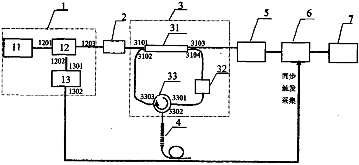
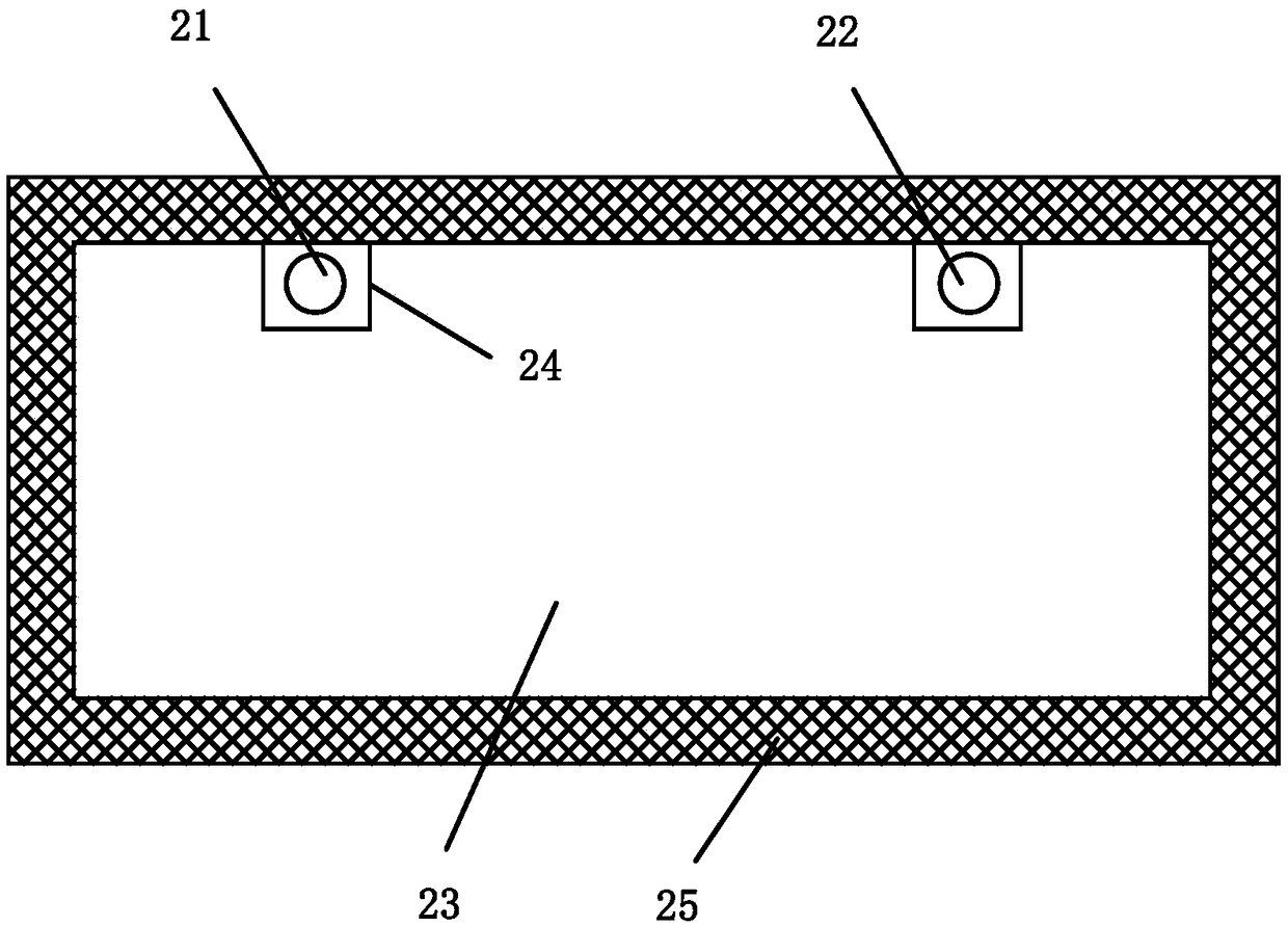
[0060] refer to Figure 1-2 , a specific embodiment of the present invention includes,

[0061] A light source module 1, the light source module 1 is composed of a tunable laser 11, an acousto-optic modulator 12 and a radio frequency modulator 13, the output terminal of the tunable laser 11 is connected to the input terminal 1201 of the acousto-optic modulator 12, The output terminal 1301 of the radio frequency modulator 13 is connected to the modulation terminal 1202 of the acousto-optic modulator 12;

[0062] More than one fiber ring down cavity, the fiber ring down cavity is made up of a fiber ring 3 and ...


PUM

PropertyMeasurementUnit
Lengthaaaaaaaaaa

Abstract

The invention discloses a distributed optical fiber sensor. The sensor comprises a light source module, more than one optical fiber ring-down cavities and a connection component. The light source module is formed by a tunable laser, an acoustic-optical modulator and a radio frequency modulator. Each optical fiber ring-down cavity is formed by an optical fiber ring and a fiber bragg grating sensingunit. The optical fiber ring at least comprises an optical fiber coupler, an erbium-doped optical fiber amplifier and an optical fiber circulator which are connected by an optical fiber. The connection component connects the output end of the acoustic-optical modulator and the first port of the optical fiber coupler. The third port of the optical fiber coupler is connected to the input end of a photoelectric detector. The output end of the photoelectric detector is connected to a signal processing and display system via a high speed data collection card. The synchronous trigger port of the high speed data collection card is connected to the second output port of the radio frequency modulator. The connection component comprises one single mode fiber and one multimode fiber. In the invention, disadvantages in the prior art can be improved and the detection precision of a temperature and a dependent variable is increased.

Description

technical field [0001] The invention relates to the technical field of electric equipment detection, in particular to a distributed optical fiber sensor. Background technique [0002] The power transformer plays an important role in the power system, and its safe operation directly affects the reliability and safety of power supply. Statistics show that insulation damage is the main cause of transformer failure, and winding is the part with the highest failure rate. The accuracy and real-time performance of winding temperature and deformation detection are of great significance to the safe operation of transformers. [0003] At present, the temperature detection methods of transformers include top oil temperature method, fluorescent optical fiber temperature measurement method and fiber Bragg grating temperature measurement method. The measurement accuracy of the top oil temperature method is low, and the measurement range is small; the temperature measurement accuracy of ...

Claims


Application Information

Patent Timeline
IPC IPC(8): G01D5/353
CPCG01D5/35316G01D5/35374G01D5/3538
Inventor 高树国刘云鹏范晓舟孙路孟令明贺鹏姜硕刘博闻
Owner STATE GRID HEBEI ELECTRIC POWER RES INST
Features
  • R&D
  • Intellectual Property
  • Life Sciences
  • Materials
  • Tech Scout
  • Unparalleled Data Quality
  • Higher Quality Content
  • 60% Fewer Hallucinations
Learn More