Fiber grating distributed strain sensor and strain monitoring method thereof
A distributed strain, fiber grating technology, applied in the direction of using optical devices to transmit sensing components, transmission monitoring/test/fault measurement systems, cladding fibers, etc., can solve complex demodulation algorithms, difficult to achieve networking, system structure It can improve the measurement accuracy and achieve the effect of high spatial resolution positioning
- Summary
- Abstract
- Description
- Claims
- Application Information
AI Technical Summary
Problems solved by technology
Method used
Image
Examples
Embodiment 2
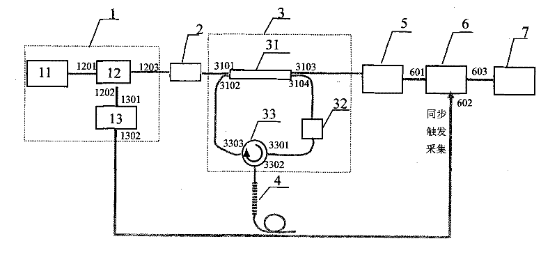
[0083] Embodiment 2, the networking system scheme based on wavelength division multiplexing is as follows Figure 4 Shown: where 1 is the light source module, using such as figure 1 The tunable laser 11 used in the structure is formed by connecting an acousto-optic modulator 12 and a radio frequency modulator 13, and outputs an optical pulse sequence. 2 is an optical connector. 3 for figure 1 Fiber optic rings in the structure. 411, 412, 413, 414... 41r are cascaded fiber grating sequences connected to the ring-down cavity through the circulator 33, and the access mode of 411 is the same as figure 1 The fiber grating sensing unit 4 in the structure is the same, and other fiber gratings are sequentially cascaded and welded behind the 411 fiber grating. Through this structure, distributed strain sensing within the gate area of multiple fiber gratings can be realized, and the distributed strain demodulation method in the gate area of each fiber grating is exactly the same...
Embodiment 3
[0086] Embodiment 3, the networking system scheme based on wavelength division multiplexing plus time division multiplexing is as follows Figure 5 Shown: where 1 is the light source module, and Figure 4 The same light source used in the structure. 31, 32, ..., 3j are as figure 1 The fiber optic ring formed in the structure. 411, 412, ... 41r; 421, 422, ... 42r; ...; 4j1, 4j2, ..., 4jr are respectively the cascaded fiber grating sequence groups connected to the optical fiber ring 31, 32 ... 3j, each stage The construction method of the fiber grating sequence is the same as that of Figure 4 The construction method is the same in the wavelength division multiplexing structure. Each optical fiber ring and the corresponding cascaded fiber grating sequence constitute a measurement channel, 2 are s optical switching channels, and the number of optical switching channels can reach 16 or even 32 channels. Using optical switching, one channel is selected each time, which channel ...
Embodiment 4
[0088] Example 4, Figure 6 It is one of the performance optimization schemes for the network system structure. In the basic structure of distributed sensing figure 1 and network structure Figure 4 Add a filtering and denoising function module on the basis of , and mainly draw the access scheme of the filtering and denoising function module, and other undrawn parts are consistent with the previous scheme. A filtering fiber grating 8 is connected to the ring-down cavity through a second optical circulator 34 . Along the propagation direction of the light pulse in the ring-down cavity, the second optical circulator 34 is connected behind the first optical fiber circulator 33 . The filter fiber grating 8 is fixed on the stress tuning or temperature tuning device, and is connected to the tunable laser 11 through the automatic synchronous trigger device 9, so as to keep the wavelength output by the light source consistent with the center reflection wavelength of the filter fiber...
PUM
 Abstract
Description
Claims
Application Information
 - R&D
- Intellectual Property
- Life Sciences
- Materials
- Tech Scout
- Unparalleled Data Quality
- Higher Quality Content
- 60% Fewer Hallucinations
Browse by: Latest US Patents, China's latest patents, Technical Efficacy Thesaurus, Application Domain, Technology Topic, Popular Technical Reports.
© 2025 PatSnap. All rights reserved.Legal|Privacy policy|Modern Slavery Act Transparency Statement|Sitemap|About US| Contact US: help@patsnap.com


