
Defect detecting device and method based on pulsed eddy current array

A defect detection and pulsed eddy current technology, which is applied in the field of defect detection devices based on pulsed eddy current arrays, can solve the problems of misjudgment of detection results, incompleteness, and inability to fully reflect defect information, etc., to reduce the interference of the magnetic field and improve the accuracy Effect

Active Publication Date: 2019-01-04
NORTHEASTERN UNIV
View PDF5 Cites 8 Cited by
  • Summary
  • Abstract
  • Description
  • Claims
  • Application Information

AI Technical Summary

Problems solved by technology

However, a single detection probe is extremely susceptible to interference from the external environment, and cannot fully reflect defect information
A single pulsed eddy current nondestructive testing cannot get rid of the influence of the lift-off effect on defect detection. The theoretical basis of pulsed eddy current has been established completely, but the design of the overall testing device is different and not perfect. If there are defects, corrosion, lift-off, etc. , will cause a lot of misjudgment of the detection results. This is a difficult problem currently faced by pulsed eddy current technology, and the research on pulsed eddy current defect classification and identification is still in its infancy, and the classification effect is not very ideal. We need to expand our research ideas and explore new method

Method used


Image

  • Defect detecting device and method based on pulsed eddy current array
  • Defect detecting device and method based on pulsed eddy current array
  • Defect detecting device and method based on pulsed eddy current array

Examples


Embodiment Construction

[0045] The specific implementation manners of the present invention will be further described in detail below in conjunction with the accompanying drawings and embodiments. The following examples are used to illustrate the present invention, but are not intended to limit the scope of the present invention.

[0046] The method of this embodiment is as follows:

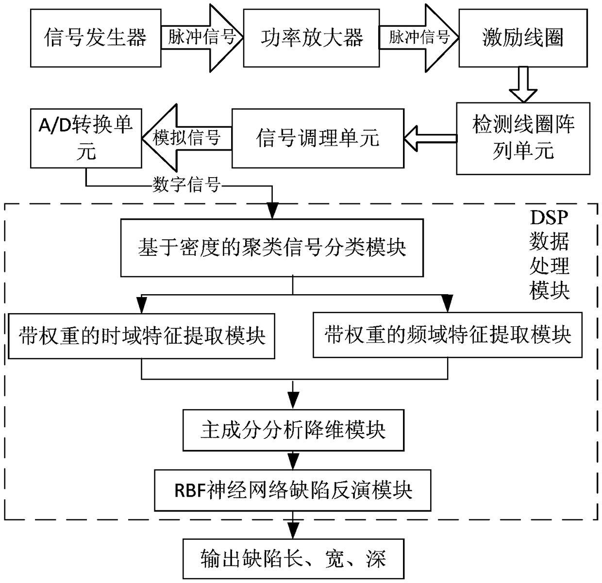
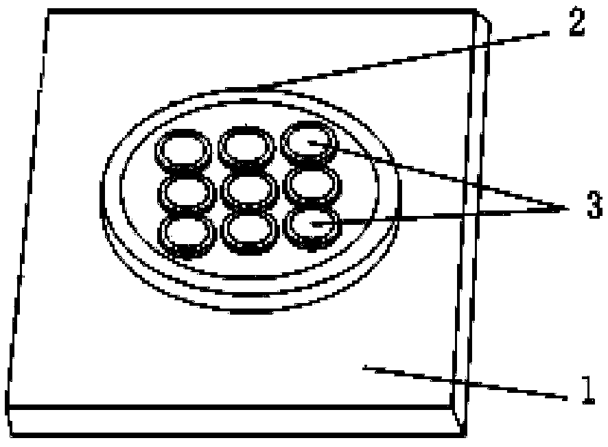
[0047] On the one hand, the present invention provides a defect detection device based on a pulsed eddy current array, such as figure 1 and figure 2 As shown, it includes: a signal generator, a power amplifier, an excitation coil, a detection coil array unit, a signal conditioning unit, an A / D conversion unit, and a DSP data processing module; the signal generator is connected to the input end of the power amplifier, and the power amplifier The output terminal of the signal conditioning unit is connected to the two ends of the excitation coil, the detection coil array unit is in the excitation coil, the input termina...


PUM


Abstract

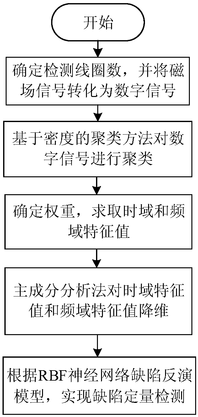
The invention provides a defect detecting device and method based on a pulsed eddy current array, and relates to the technical field of non-destructive testing. The defect detecting method comprises the following course that a signal generator produces a periodic pulse signal, after being amplified by a power amplification machine, the periodic pulse signal is applied to two ends of an exciting coil; a test coil array unit acquires a magnetic field signal above a piece to be tested, and transports the magnetic field signal to a signal conditioning unit; the signal conditioning unit is used forperforming filtering and amplifying on the signal, and transporting the treated signal to an A / D converting unit; and finally, the signal is transported to a DSP data processing module to seek dimension information of defects. According to the defect detecting device disclosed by the invention, clustering treatment and equalizing treatment are performed on detection array data, so that the influence of inclination or lifting-off of the detection array coil on defect detection is effectively restrained; a structure that a coil is used for exciting, and an array is formed by a plurality of testcoils is adopted, so that the interference of a magnetic field is reduced, and comprehensive defect information detection is also realized; and the time domain characteristic quantity and the frequency domain characteristic quantity are combined, so that the defect detecting accuracy is improved.

Description

technical field [0001] The invention relates to the technical field, in particular to a defect detection device and method based on a pulsed eddy current array. Background technique [0002] At present, the operating life of most of the pipelines in our country has reached more than 20 years. Due to stress, man-made or natural factors, various defects will occur in the operation of the pipelines that are running all the year round. The defects of the pipelines in operation will cause leakage accidents. , will cause huge safety hazards in production, so it is necessary to carry out effective inspections on in-service pipelines. Pulsed eddy current detection technology is the main research direction of defect detection. It is a non-destructive and non-contact detection method based on eddy current effect and does not require couplant. It has a very wide range of applications. However, a single detection probe is extremely susceptible to interference from the external environm...

Claims


Application Information

Patent Timeline
Patent Type & Authority Applications(China)
IPC IPC(8): G01N27/90G01B7/02G01B7/26
CPCG01B7/02G01B7/26G01N27/904G01N27/9046
Inventor 冯健邱帅汪刚刘金海马大中张化光卢森骧吴振宁
Owner NORTHEASTERN UNIV
Learn More