
Heat pipe cooling nuclear reactor power system based on uranium hydrogen yttrium fuels and dynamic thermoelectric conversion

A thermoelectric conversion and nuclear reactor technology, applied in the field of nuclear power, can solve the problems of coolant loss accidents, failure to fundamentally eliminate coolant loss accidents, increase in system quality, volume and complexity, etc.

Pending Publication Date: 2019-01-04
CHINA INSTITUTE OF ATOMIC ENERGY
View PDF4 Cites 21 Cited by
  • Summary
  • Abstract
  • Description
  • Claims
  • Application Information

AI Technical Summary

Problems solved by technology

[0005] Although the various types of loop-cooled and heat pipe-cooled nuclear reactor power systems listed above are far superior to fossil fuel heat engines, chemical batteries, solar cells, and radioisotope batteries in terms of energy density, operating life, power range, and environmental adaptability, etc. , but at the same time there are some inherent defects, such as the loop cooling reactor can not fundamentally eliminate the loss of coolant accident (LOFA) and loss of coolant accident (LOCA), the use of UO 2 Fuel such as fuel or UN cannot avoid serious consequences such as core meltdown that may be caused by a positive reactivity introduction accident (RIA). In turn, it will inevitably lead to an increase in the quality, volume and complexity of the system

Method used


Image

  • Heat pipe cooling nuclear reactor power system based on uranium hydrogen yttrium fuels and dynamic thermoelectric conversion
  • Heat pipe cooling nuclear reactor power system based on uranium hydrogen yttrium fuels and dynamic thermoelectric conversion
  • Heat pipe cooling nuclear reactor power system based on uranium hydrogen yttrium fuels and dynamic thermoelectric conversion

Examples


Embodiment Construction

[0023] The present invention will be described in detail below in conjunction with the accompanying drawings and embodiments.

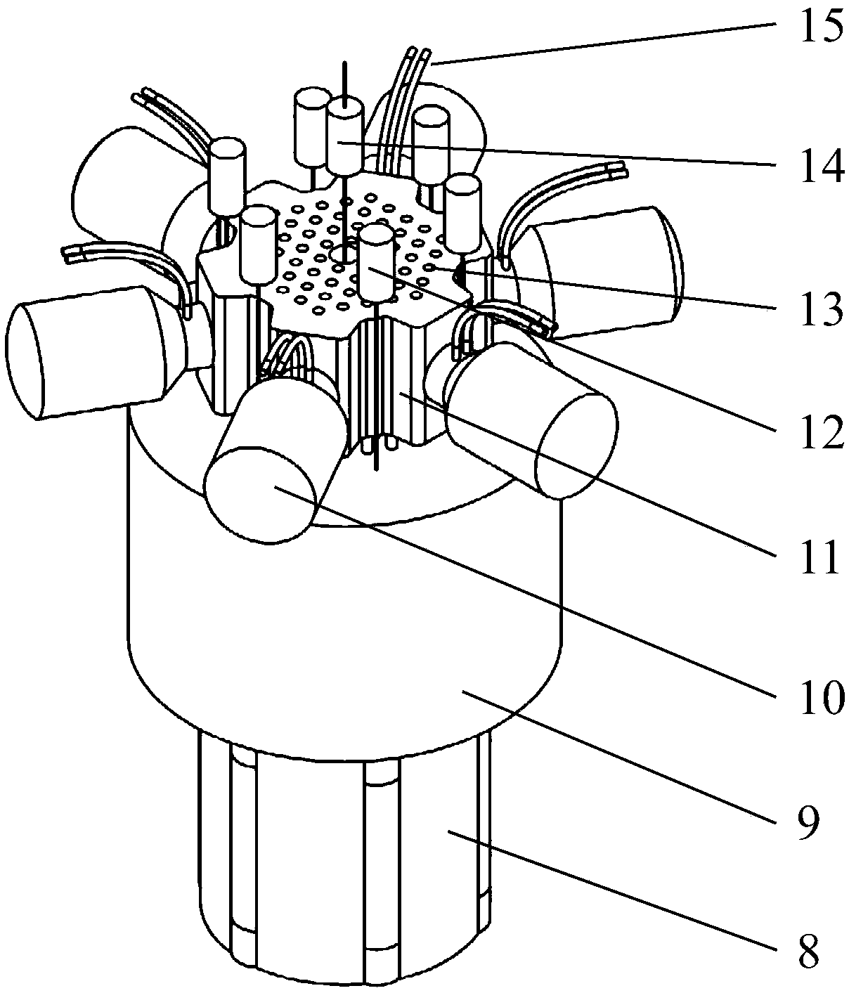
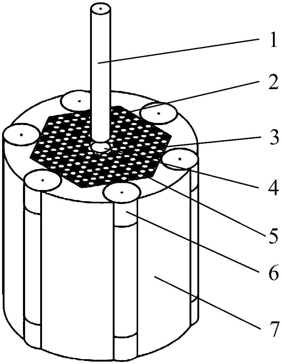
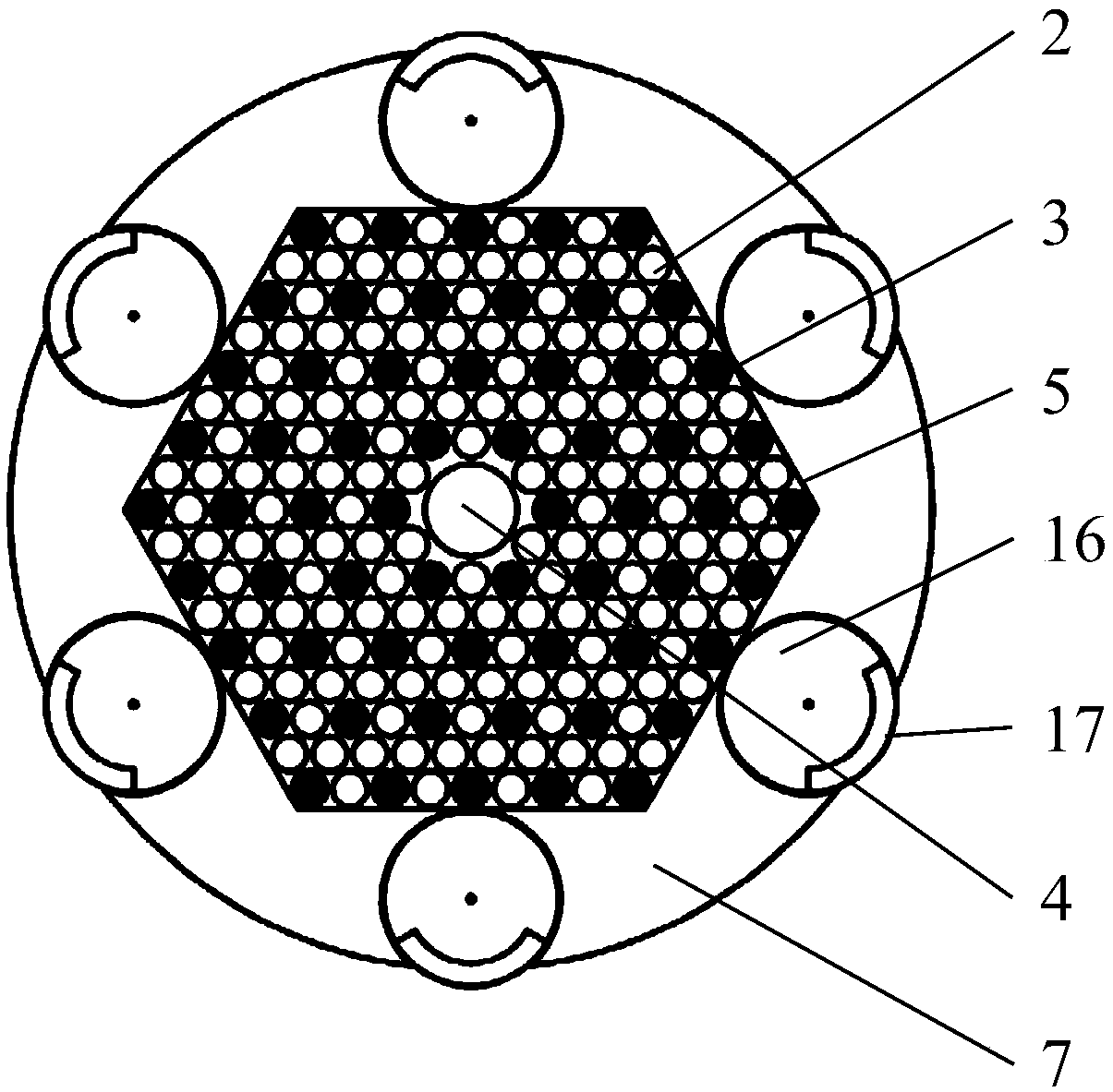
[0024] Such as figure 1 As shown, the present invention provides a heat pipe cooling nuclear reactor power system based on uranium hydrogen yttrium fuel and dynamic thermoelectric conversion, including a heat pipe 13, a reactor 8 arranged inside the shield 9, and a control drum drive arranged outside the shield 9 Mechanism 12, heat exchanger 11 and safety rod driving mechanism 14; one end of the heat pipe 13 extends into the heat pipe tunnel 3 of the reactor 8, and the other end passes through the shield 9 and is inserted into the heat exchanger 11; the heat exchanger 11 is connected to the free-piston Stirling generator 10; the control drum driving mechanism 12 and the safety rod driving mechanism 14 are drivingly connected to the control drum 6 and the safety rod 1 of the reactor 8 respectively. The heat pipe 13 is a liquid metal heat pipe. The he...


PUM


Abstract

The invention relates to a heat pipe cooling nuclear reactor power system based on uranium hydrogen yttrium fuels and dynamic thermoelectric conversion. The heat pipe cooling nuclear reactor power system comprises a heat pipe, a reactor, a control drum driving mechanism, a heat exchanger and a safety rod driving mechanism, wherein the reactor is arranged on the inner side of a shield, and the control drum driving mechanism is arranged on the outer side of the shield. One end of the heat pipe extends into a heat pipe duct of the reactor, the other end of the heat pipe penetrates the shield andis inserted into the heat exchanger, the heat exchanger is connected with a free piston Stirling generator, and the control drum driving mechanism and the safety rod driving mechanism are connected with a control drum and a safety rod of the reactor in a driving manner. The heat pipe cooling nuclear reactor power system has the advantages that safety of uranium hydrogen zirconium fuels and heat pipe cooling modes is sufficiently combined, safety of long-term running under unmanned monitoring conditions is ensured, a system structure is sufficiently simplified, environmental adaptability and deployment flexibility are improved, and the requirements of various maritime activities for energy with the level of ten kilowatts and below can be effectively met.

Description

technical field [0001] The invention belongs to the field of nuclear power, in particular to a heat pipe cooling nuclear reactor power supply system based on uranium hydrogen yttrium fuel and dynamic thermoelectric conversion. Background technique [0002] For special mission environments such as remote areas, isolated islands, deep oceans, and outer space, nuclear reactor power supplies have incomparable performance advantages over fossil fuel heat engines, chemical batteries, solar cells, and radioisotope batteries. For high energy density, long operating life, wide power range, strong environmental adaptability, etc. According to the core cooling method, nuclear reactor power supply can be roughly divided into two types: loop cooling type and heat pipe cooling type. [0003] Loop-cooled nuclear reactor power uses a fluid (liquid or gas) cooling loop to divert the fission heat from the reactor core and convert it into electricity. The document "SP-100 Space Reactor Desig...

Claims


Application Information

Patent Timeline
Patent Type & Authority Applications(China)
IPC IPC(8): G21C3/58G21C15/28G21D1/02
CPCG21C3/58G21C15/28G21D1/02Y02E30/30Y02E30/00
Inventor 孙晓博胡古安伟健葛攀和郭键高剑
Owner CHINA INSTITUTE OF ATOMIC ENERGY
Learn More