Battery module

A technology of battery modules and modules, which is applied to battery pack components, secondary batteries, small-sized batteries/battery packs, etc., and can solve problems affecting battery quality, unguaranteed welding quality, and poor bonding performance, etc. problems, to achieve the effects of diversified splicing methods, convenient structure disassembly and assembly, and reduced processing costs

Pending Publication Date: 2019-01-04
KUSN JINXIN NEW ENERGY TECH
View PDF20 Cites 1 Cited by
  • Summary
  • Abstract
  • Description
  • Claims
  • Application Information

AI Technical Summary

Problems solved by technology

However, when the terminal of this structure is welded together with the copper sheet, the pole, and the lead sleeve, the poor bonding performance between the surface oxide layer of the terminal copper sheet and the melted lead liquid will often cause virtual welding, so that the welding quality cannot be guaranteed and affect the battery life. quality

Method used


Image

  • Battery module
  • Battery module
  • Battery module

Examples


Embodiment 1

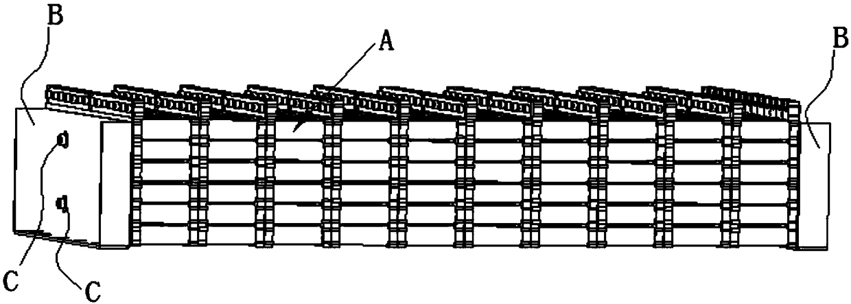
[0060] Embodiment 1: a battery module, such as Figure 2-Figure 6 with Figure 12-Figure 20 As shown, it includes a plurality of single battery modules A, an external frame B and a connecting shaft C, the external frame B is located on the left and right sides of the battery module, and the connecting shaft C connects the multiple single cells The module and the external cage are fixed in series, and the connection shaft, multiple single battery molds and the external cage are fixed through the nuts at both ends of the connecting shaft;

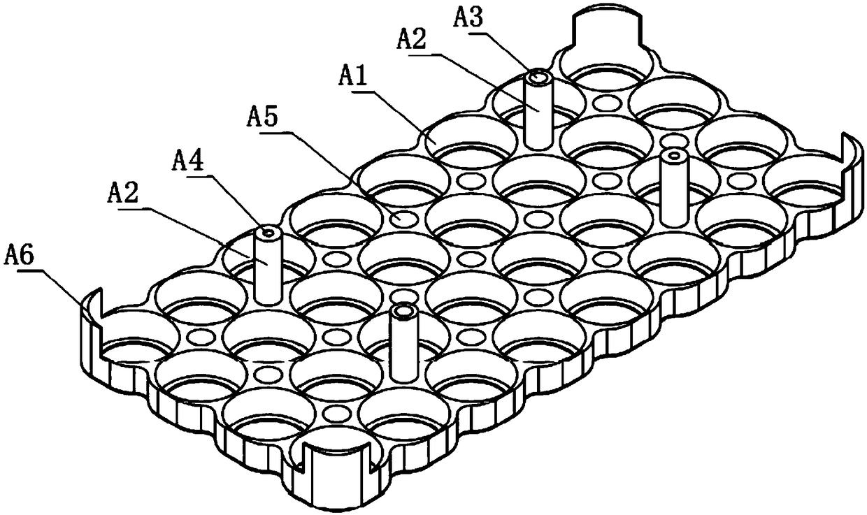
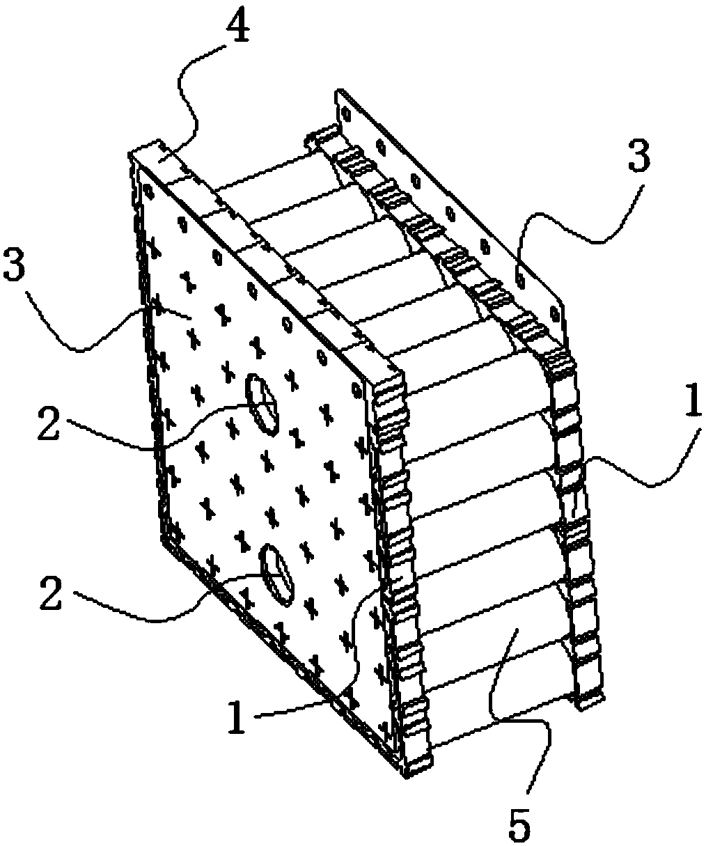
[0061] Each single battery module A includes two battery fixing substrates 1, a hollow connecting column 2 connecting the two battery fixing substrates, a bus bar 3 and a bus bar fixing frame 4, and the bus bar 3 and the bus bar fixing frame 4 fixedly connected, the bus bar fixing frame 4 is plugged and fixed with the battery fixing substrate 1;

[0062] On either side of the two adjacent sides of the battery fixing substrate 1, a number of...

Embodiment 2

[0079] Embodiment 2: a battery module, such as Figure 7-Figure 20 As shown, the rest is the same as that of Embodiment 1, the difference is that: the structure for realizing the insertion and fixing of the busbar fixing frame and the battery fixing substrate is: the busbar of this fixing method is L-shaped, and the busbar The rear side wall of the fixing frame is provided with a second plug port 45, and the second plug port 45 is formed by extending downward from the upper end of the rear side wall of the bus bar fixing frame, and the upper end of the battery fixing base plate is provided with a second plug port. Plug posts with matching interfaces.

[0080] The second socket 45 is a socket with a closed end.

[0081] The working principle of the present invention is as follows:

[0082] First use the plug-in grooves and plug-in bumps of the battery-fixed base plate to arbitrarily splice out the size of the required battery-fixed plate, and place the lithium battery in the ...


PUM


Abstract

The invention discloses a battery module, which comprises a plurality of single battery modules. Each cell module comprises two cell fixing substrates, a hollow connecting post, a bus piece and a buspiece fixing frame. Fixing holes and weight-reducing blind holes are arranged on the battery fixing substrate; The connecting post comprises a lower sleeve part, a middle sleeve part and an upper sleeve part. The upper end of the upper sleeve part forms a pillar, and the lower end of the lower sleeve part forms a positioning hole matched with the pillar. The busbar comprises a positioning hole, awelding point and a connecting hole, and screws pass through the positioning hole and the screw hole in turn to realize the fixation of the busbar and the fixing frame of the busbar; The connecting shaft passes through the through hole and the connecting hole of the battery fixing substrate to realize the serial fixation of the battery fixing substrate and the bus piece. The invention not only canarbitrarily splice out different specifications of battery fixing substrates, but also realizes serial fixation of a plurality of battery fixing substrates through connecting pillars and connecting shafts. But also can quickly realize the current confluence of adjacent cell modules, improve the assembly efficiency and reduce the production cost.

Description

technical field [0001] The invention belongs to the technical field of batteries, in particular to a battery module. Background technique [0002] Lithium batteries are more and more widely used in our daily life. With different production processes and different usage requirements, lithium batteries have produced many different packaging forms, such as square soft pack lithium batteries, square metal shell lithium batteries, round Shaped metal shell lithium batteries, etc. Among them, packages represented by circular metal shell lithium batteries are widely used in notebook computers, electric bicycles, electric motorcycles, electric vehicles, electric tools and other fields. [0003] Usually, several lithium batteries are connected in parallel or connected in series to realize work, which requires fixing several lithium batteries. Chinese patent CN 202503048 U discloses a "cylindrical lithium battery support", including: a support body, a plurality of cell fixing seats A1...

Claims


Application Information

Patent Timeline
Patent Type & Authority Applications(China)
IPC IPC(8): H01M2/02H01M2/22H01M10/0525H01M50/10H01M50/528
CPCH01M10/0525H01M50/10H01M50/528Y02E60/10
Inventor 何阳张晓红
Owner KUSN JINXIN NEW ENERGY TECH
Why Eureka
Try Eureka