
Three-stage synchronous machine rotor position estimation system and estimation method

A rotor position, synchronous motor technology, applied in the control system, motor control, electronic commutator, etc., can solve the problems of motor starting torque ripple, complex control structure, large load, etc., to reduce volume and complexity , Improve the effect of stability and reliability

Active Publication Date: 2019-01-04
NANJING UNIV OF AERONAUTICS & ASTRONAUTICS
View PDF6 Cites 8 Cited by
  • Summary
  • Abstract
  • Description
  • Claims
  • Application Information

AI Technical Summary

Problems solved by technology

However, under severe aviation conditions with large temperature changes and electromagnetic interference, the problem of inaccurate position detection or even failure of the sensor will occur, and the setting of the sensor increases the volume, weight and cost of the system. Therefore, the start-up control without position sensor Research is the key direction for the development of three-stage synchronous motors
[0004] The traditional position estimation methods in the starting stage can be divided into two types. One is the rotor pre-positioning method, which makes the d-axis of the rotor coincide with the phase A by applying a specific angle voltage vector. However, the three-stage synchronous motor is connected to the engine, always There is a large load, and it is difficult to achieve rotor pre-positioning; the other is to use the structural characteristics of the salient poles of the main generator rotor to inject high-frequency, low-frequency sine or square waves and other signals, and finally extract the rotor position from the stator end of the motor. The information signal can be used to calculate the rotor position and angle. However, the additional injection of the signal will inevitably lead to the starting torque ripple of the motor, and the control structure is complicated.

Method used


Image

  • Three-stage synchronous machine rotor position estimation system and estimation method
  • Three-stage synchronous machine rotor position estimation system and estimation method
  • Three-stage synchronous machine rotor position estimation system and estimation method

Examples


Embodiment Construction

[0058] The technical solution of the present invention will be described in detail below in conjunction with the accompanying drawings and specific embodiments.

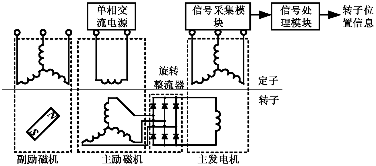
[0059] Such as figure 1 As shown, the three-stage synchronous motor rotor position estimation system and estimation method of the present invention include a three-stage synchronous motor, a single-phase AC power supply, a signal acquisition module and a signal processing module, wherein the three-stage synchronous motor includes an auxiliary exciter , the main exciter, the rotating rectifier and the main generator, the auxiliary exciter is not involved in the present invention, and the main exciter, the rotating rectifier and the main generator are coaxially arranged; the main exciter is a rotating armature type electric excitation synchronous motor, The stator is a DC excitation winding, and the rotor side is an armature winding; the stator side of the main generator is an armature winding, and the rotor side is an...


PUM


Abstract

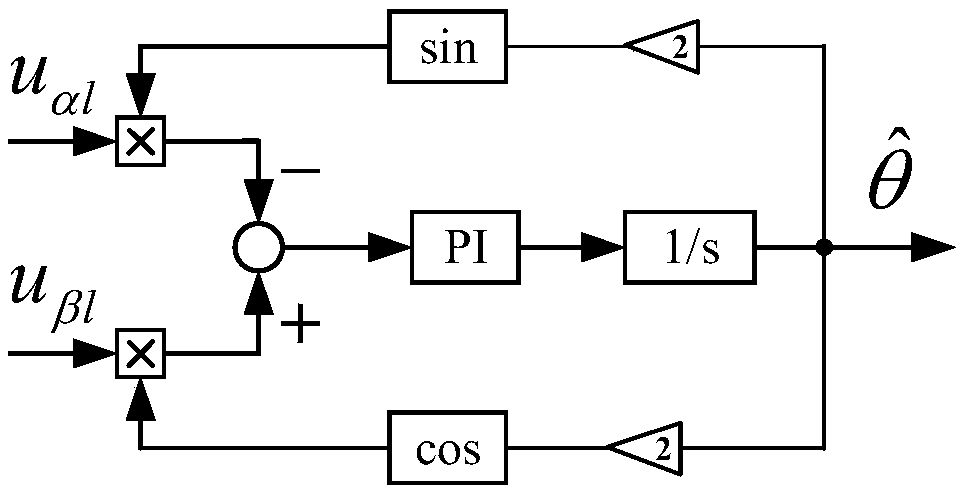
The invention discloses a three-stage synchronous motor rotor position estimation system and an estimation method. The system comprises a three-stage synchronous motor, a single-phase AC power supply,a signal acquisition module and a signal processing module. The three-stage synchronous motor comprises a main exciter, a rotary rectifier and a main generator coaxially arranged. The single-phase alternating current power supply leads the excitation winding of the main exciter into the single-phase alternating current to generate pulsating magnetic field, A three-phase alternating current is induced in the armature winding of the main exciter, After pssing the rotary rectifier, the excitation winding of the main generator is supplied with power, and a high-frequency signal containing rotor position information is induced in the armature winding of the main generator. The signal acquisition module extracts the high-frequency signal containing rotor position information, and then the rotorposition angle is estimated through the signal processing module. As that invention does not require additional injection of other signals, the output torque fluctuation of the motor introduce by thetraditional high-frequency signal injection method is avoided, and the invention has good robustness and stability.

Description

technical field [0001] The invention belongs to the technical field of motor control, in particular to a three-stage synchronous motor rotor position estimation system and estimation method. Background technique [0002] In recent years, the frequency conversion AC power system has been widely used in multi-electric and all-electric aircraft, and has become the main direction of the development of aviation power technology. In the aviation and military fields, the reliability of the power supply system is high, and the brushless excitation synchronous motor of the rotary rectifier type uses the output of the main exciter to excite the main generator after rectification, and the brush slip ring structure is abandoned. Reliability is improved to a certain extent. Since the main generator is connected to the engine, it has the function of starting / generating integration, which saves additional starting device, saves space and cost. At present, many civil aircraft and fighter j...

Claims


Application Information

Patent Timeline
IPC IPC(8): H02P6/18H02P6/10
CPCH02P6/10H02P6/183H02P2203/11
Inventor 魏佳丹薛哗鲁恒周波
Owner NANJING UNIV OF AERONAUTICS & ASTRONAUTICS
Learn More