
Non-oscillating comparator

A comparator and comparison circuit technology, applied in high-frequency amplifiers, pulse technology, multiple input and output pulse circuits, etc., can solve problems such as complex comparators and comparator output delays

Active Publication Date: 2019-01-04
STMICROELECTRONICS (GRENOBLE 2) SAS +1
View PDF0 Cites 0 Cited by
  • Summary
  • Abstract
  • Description
  • Claims
  • Application Information

AI Technical Summary

Problems solved by technology

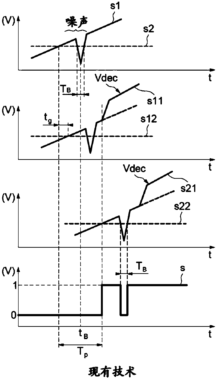
[0036] However, the filtering means requires an additional clock of a higher frequency than the operating frequency of the comparator in order to avoid that the output of the comparator exhibits a delay, and the filtering means requires additional circuitry
[0037] These additional components result in an additional power dissipation of about twice that of the comparator CHF and make the comparator more complex

Method used


Image

  • Non-oscillating comparator
  • Non-oscillating comparator
  • Non-oscillating comparator

Examples


Embodiment Construction

[0055] refer to Figure 4 and Figure 5 , which shows an exemplary embodiment of the comparison circuit COMP and the latch stage 30 .

[0056] These figures show an input interface comprising terminals E1 and Eref receiving input signals s1 and s2, an amplifier comprising preamplifier means 1 and gain amplifier means 2 linked to each other as described above.

[0057] The comparison circuit COMP additionally comprises an output interface comprising a terminal SCOMP for delivering the output signal sCOMP and a latch stage 30 comprising a first input terminal E301 linked to the output S21, linked to the output S22 and an output terminal S30 linked to the output terminal SCOMP of the comparison circuit COMP and the input Ec of the preamplifier device 1 .

[0058] Advantageously, the comparison circuit COMP is an example of a high-frequency comparator in which the first propagation duration Tp of the signals s1 and s2 at the inputs E1 and Eref is for example shorter than 5 ns. ...


PUM


Abstract

The invention discloses a non-oscillating comparator. A comparison circuit includes an input interface configured to receive input signals and an output interface configured to deliver an output signal. A comparator is coupled between the input interface and the output interface. An amplifier is coupled between the input interface and the comparator. A neutralization circuit is configured to neutralize any change of state of the output signal starting from each moment in time at which the change of state of the output signal occurs and lasting for a second duration of propagation that compensates for a duration of propagation of signals within the amplifier.

Description

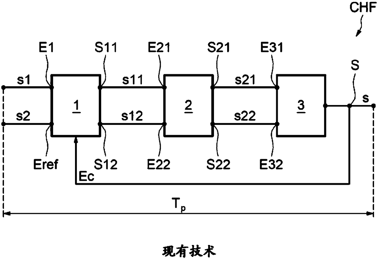
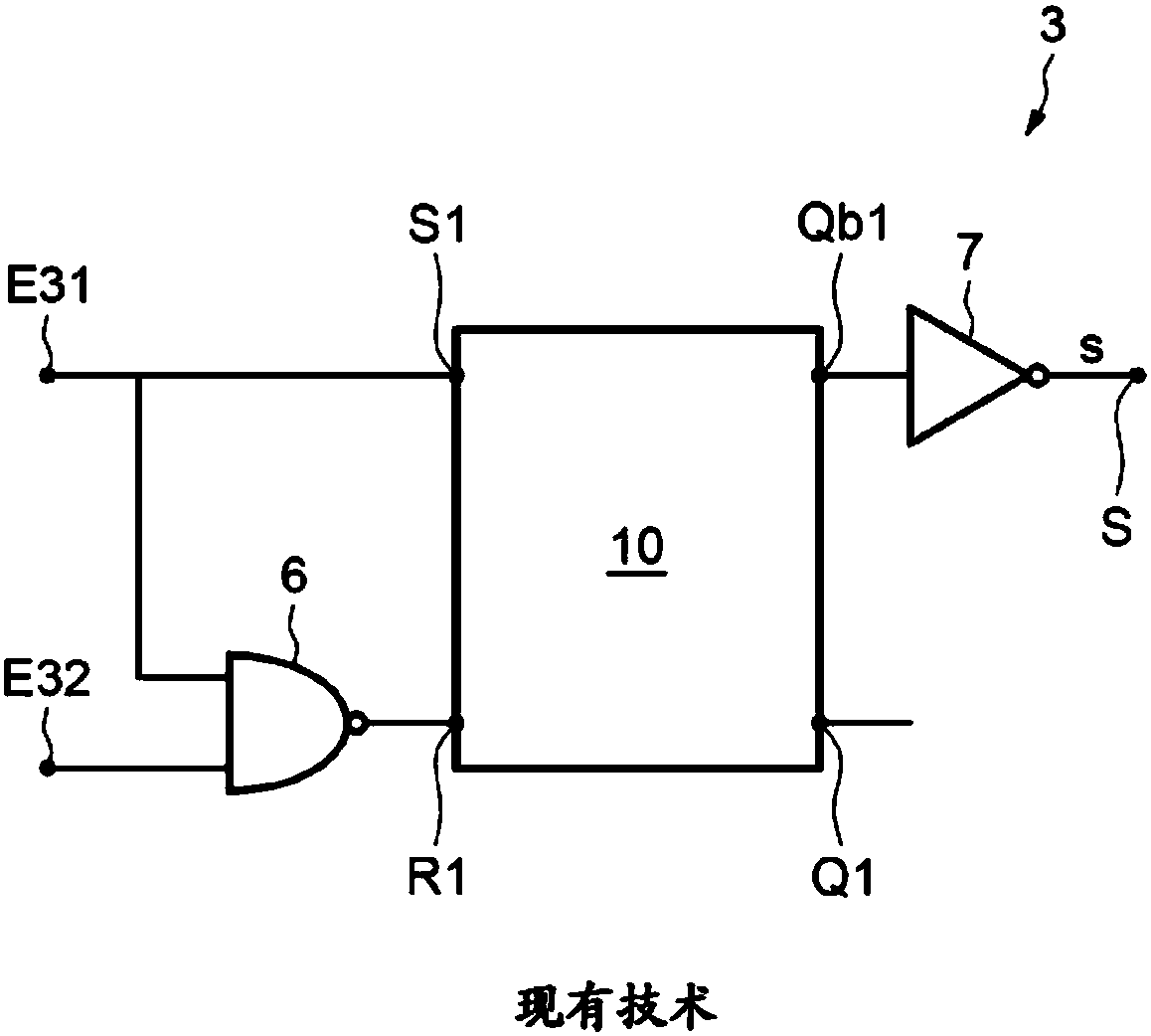
[0001] Cross References to Related Applications [0002] This application claims priority from French patent application No. 1755922 filed June 28, 2017, which is hereby incorporated by reference. technical field [0003] Embodiments of the invention relate to comparator devices. Background technique [0004] figure 1 An example of a comparator CHF according to the prior art is shown. [0005] The comparator CHF comprises an input interface comprising input terminals E1 and Eref and an output interface comprising an output terminal S. [0006] The comparator also includes an amplifier comprising preamplifier means 1 and a gain amplifier indicated by reference numeral 2 . [0007] The preamplifier means 1 comprise inputs connected to terminals E1 and Eref and outputs S11 and S12 respectively connected to inputs E21 and E22 of the gain amplifier means 2 . [0008] The comparator CHF comprises a latch stage 3 comprising inputs E31 and E32 connected to the outputs S21 and ...

Claims


Application Information

Patent Timeline
IPC IPC(8): H03K3/013H03K3/0233
CPCH03K3/013H03K3/0233H03K3/02337H03K5/1252H03K5/24H03K19/20H03K2005/00019H03F3/19
Inventor V·比内D·切斯诺
Owner STMICROELECTRONICS (GRENOBLE 2) SAS
Learn More