Buried new energy vehicle charging pile with water flooding prevention function

A new energy vehicle, buried technology, applied in electric vehicle charging technology, charging stations, electric vehicles and other directions, can solve the problem of battery cooling technology not achieving synchronous improvement, affecting the working life of car batteries, and charging piles being damaged by water. , to achieve the effect of improving service life, avoiding occupation, and preventing crash

Active Publication Date: 2019-01-08
ANHUI YI WEISS NEW ENERGY TECH
View PDF5 Cites 15 Cited by
  • Summary
  • Abstract
  • Description
  • Claims
  • Application Information

AI Technical Summary

Problems solved by technology

[0003] In related technologies, the fast charging technology of new energy vehicles is becoming more and more mature, and the car battery can be fully charged in just a few minutes. However, the matching battery heat dissipation technology has not been improved synchronously, and the battery heating caused by fast charging is a serious problem. , which greatly affects the working life of the car battery. At the same time, the chassis of the car will stick to mud and dust when the car is running. Large impact, it will cause a fire in severe cases
[0004] For the existing buried charging piles, in rainy weather, the main body of the charging piles is prone to water ingress due to the impeded drainage, resulting in damage to the charging piles due to long-term soaking in water

Method used


Image

  • Buried new energy vehicle charging pile with water flooding prevention function
  • Buried new energy vehicle charging pile with water flooding prevention function
  • Buried new energy vehicle charging pile with water flooding prevention function

Examples


Embodiment 1

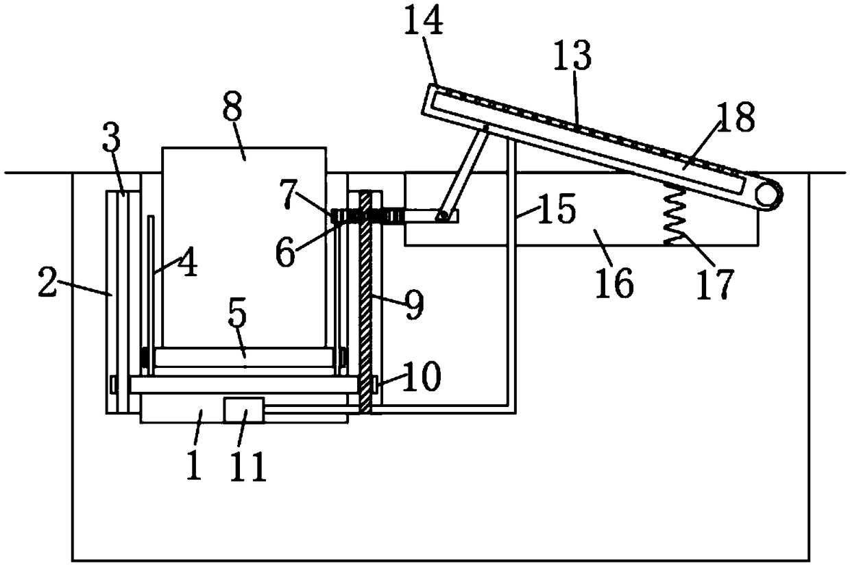
[0025] refer to figure 1 , an underground new energy vehicle charging pile with anti-flooding function, comprising a first groove 1 and a second groove 16 arranged on the ground, the opposite inner walls of the first groove 1 are provided with chute 2, A guide rod 3 and a threaded rod 9 are respectively fixedly connected between the inner top and the inner bottom of the two chute 2, the guide rod 3 and the threaded rod 9 are jointly provided with a slide plate 10, the slide plate 10 is slidably connected with the guide rod 3, and the slide plate 10 is threadedly connected with the threaded rod 9, and the upper end part of the slide plate 10 located in the first groove 1 is fixedly connected with a vertical rod 4, and the two vertical rods 4 are jointly sleeved with a buoyancy plate 5. When it is raining, rainwater enters In the first groove 1, the upper end of the buoyancy plate 5 is fixedly connected with the charging pile body 8. Under the action of the buoyancy plate 5, the...

Embodiment 2

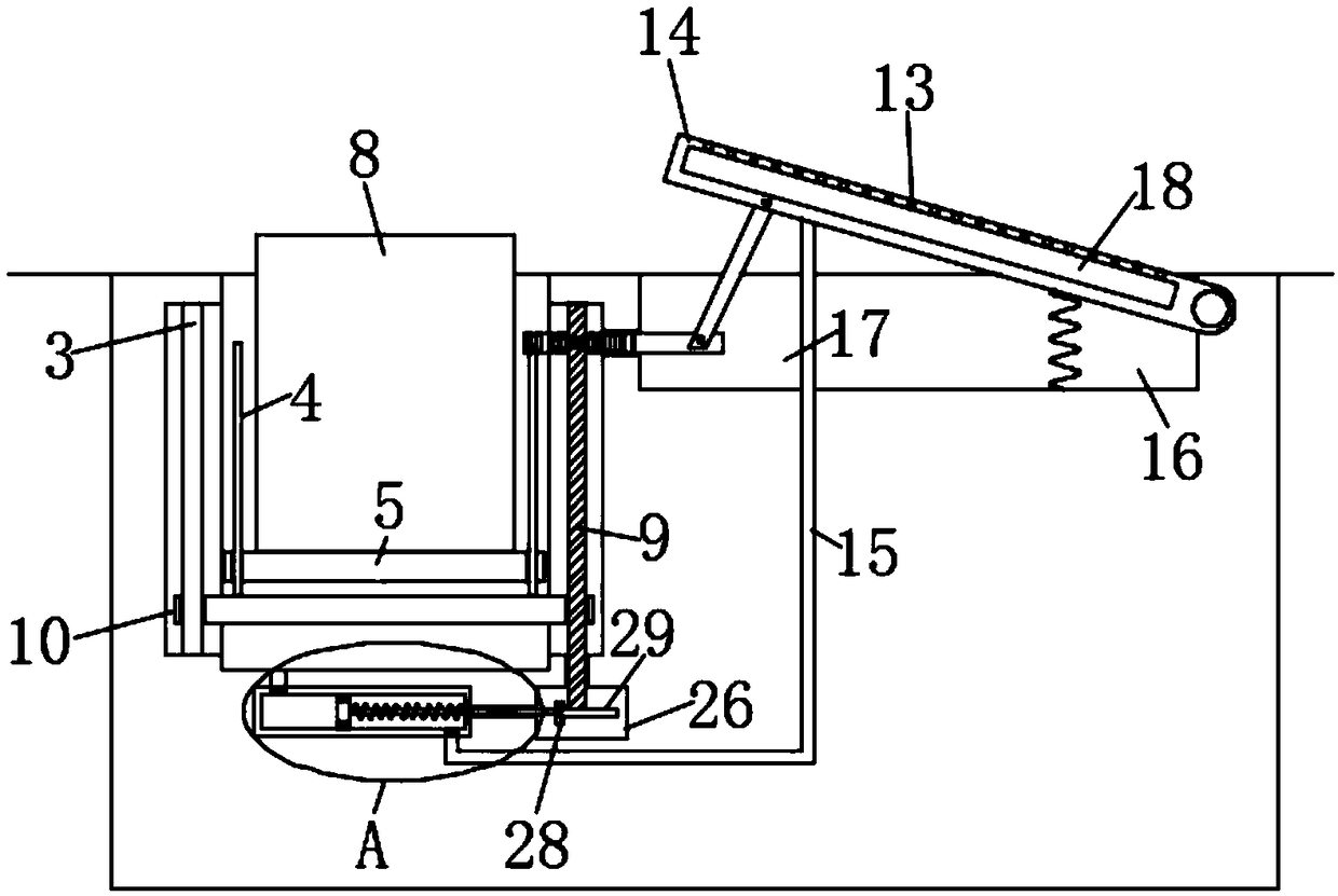
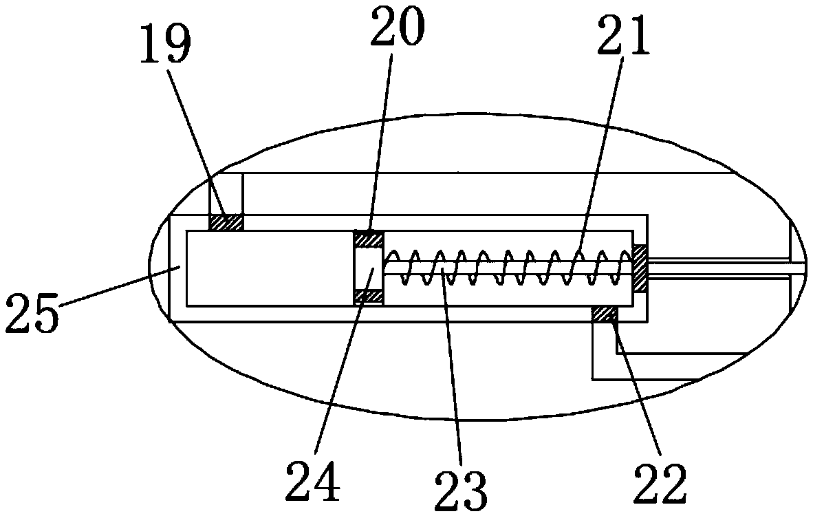
[0028] refer to Figure 2-3, the pumping mechanism includes a cylinder 25 buried under the ground, and a sliding plug 24 is sealed and slidably connected in the cylinder 25. The first one-way valve 20 that only allows water to flow from left to right is installed on the sliding plug 24, and the cylinder 25 The left upper end of the cylinder 25 communicates with the lower end of the first groove 1 and a second one-way valve 19 that only allows water to enter the cylinder 25 is installed at the communication place, and the lower right end of the cylinder 25 communicates with the cavity 18 through the conduit 15 and The connection between the conduit 15 and the cylinder 25 is installed with a third one-way valve 22 that only allows water to enter the conduit 15. The side wall of the slide 24 is fixedly connected with the slide rod 23 coaxially. A device chamber 26 is provided under the ground. The lower end of the threaded rod 9 runs through the inner bottom of the chute 2 and ex...

Embodiment 3

[0031] refer to Figure 4 , the part of the conduit 15 located in the second groove 16 is connected with a rubber water storage bag 27. When water enters the rubber water storage bag 27 from the cylinder 25, it cannot quickly flow out from the rubber water storage bag 27, and the water stays In the rubber water storage bag 27, the rubber water storage bag 27 is inflated, and the aperture of the communication part between the rubber water storage bag 27 and the cavity 18 is much smaller than the aperture of the communication part of the conduit 15 and the rubber water storage bag 27.

[0032] The difference from Example 2 is that the water in the first groove 1 is pressed into the rubber water storage bag 27, and as the rubber water storage bag 27 gradually restores its deformation, the water in the cavity 18 continues to spray from the water spray hole 13. Out, washing the chassis of the car not only removes mud and dust, but also continuously moistens and cools the chassis of...


PUM


Abstract

The invention discloses a buried new energy vehicle charging pile with water flooding prevention function. The buried new energy vehicle charging pile includes a first groove and a second groove disposed on the ground, the opposite inner walls of the first groove are provided with sliding grooves. A guide rod and a threaded rod are fixedly connected between the inner top and the inner bottom of the two sliding grooves. The guide rod and the threaded rod are sleeved together with a sliding plate, the sliding plate is slidably connected with the guide rod, the sliding plate is threadably connected with the threaded rod, the upper end part of the sliding plate in the first groove is fixedly connected with the vertical rod, two vertical rods are sleeved together with a buoyancy plate, and theupper end of the buoyancy plate is fixedly connected with the charging pile body. The invention effectively prevents the charging pile body from being submerged by water, solves the problem that in rainwater weather, the charging pile body enters water due to the water drainage blockage, and continuously sprays water on the vehicle chassis to lower the temperature of the battery when charging, thereby effectively reducing the temperature of the battery when charging, and prolonging the service life of the battery of the new energy vehicle.

Description

technical field [0001] The invention relates to the technical field of charging piles, in particular to an underground new energy vehicle charging pile with the function of preventing flooding. Background technique [0002] As the global energy crisis continues to aggravate and environmental pressure continues to increase, new energy vehicles have received widespread attention and attention from the international community, especially the huge impact of the international financial crisis on the automobile industry, driving countries around the world to accelerate the strategic transformation of transportation energy, New energy vehicles have become an important direction for future automotive development. [0003] In related technologies, the fast charging technology of new energy vehicles is becoming more and more mature, and the car battery can be fully charged in just a few minutes. However, the matching battery heat dissipation technology has not been improved synchronou...

Claims


Application Information

Patent Timeline
Patent Type & Authority Applications(China)
IPC IPC(8): B60L53/31
CPCY02T90/16Y02T90/167Y02T10/70Y02T90/12Y02T10/7072Y04S30/12
Inventor 叶烨
Owner ANHUI YI WEISS NEW ENERGY TECH
Why Eureka
Try Eureka