
Low-noise oil-gas separation type cylinder head cover assembly

A cylinder head cover, separation type technology, applied in the direction of engine components, machines/engines, shells, etc., can solve the problems of cylinder head cover failure, high processing cost, easy to crack, etc., to improve the overall structural strength, low-cost oil and gas Good effect of separation and connection strength

Pending Publication Date: 2019-01-08
鼎欣吉盛科技(浙江)有限公司
View PDF7 Cites 2 Cited by
  • Summary
  • Abstract
  • Description
  • Claims
  • Application Information

AI Technical Summary

Problems solved by technology

[0003] The traditional cylinder head cover assembly is provided with a groove in the middle, and there are many through holes in the middle of the groove, which are used to install the ignition coil. The inner cavity is equipped with a complicated oil-gas separation structure. When washing the car, the water guide function in the groove of the cylinder head cover is not good, so that the cylinder head cover retains a large amount of water, which can only be evaporated by natural evaporation or the heat generated by the engine when driving. Corrosion causes accumulated water to flow into the engine, causing failure of the cylinder head cover, diluting engine oil by water entering the crankcase, and wear of engine parts; (2) The internal strength of the cylinder head cover decreases after the through hole is opened, and the car encounters bumps during driving Under road conditions, cracks are likely to occur at the through hole of the cylinder head cover, which reduces the service life of the cylinder head cover; (3) the existing oil-gas separation type cylinder head cover has a complex labyrinth structure and high processing costs

Method used


Image

  • Low-noise oil-gas separation type cylinder head cover assembly
  • Low-noise oil-gas separation type cylinder head cover assembly
  • Low-noise oil-gas separation type cylinder head cover assembly

Examples


Embodiment Construction

[0027] The present invention will be further described below in conjunction with the accompanying drawings and specific embodiments (embodiments). The specific embodiments described here are only used to explain the present invention, but not as a basis for limiting the present invention.

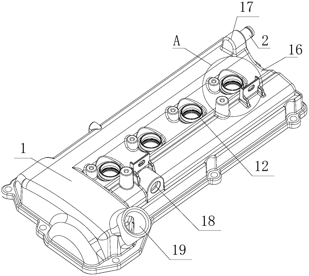
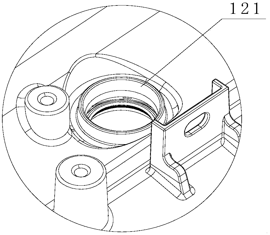
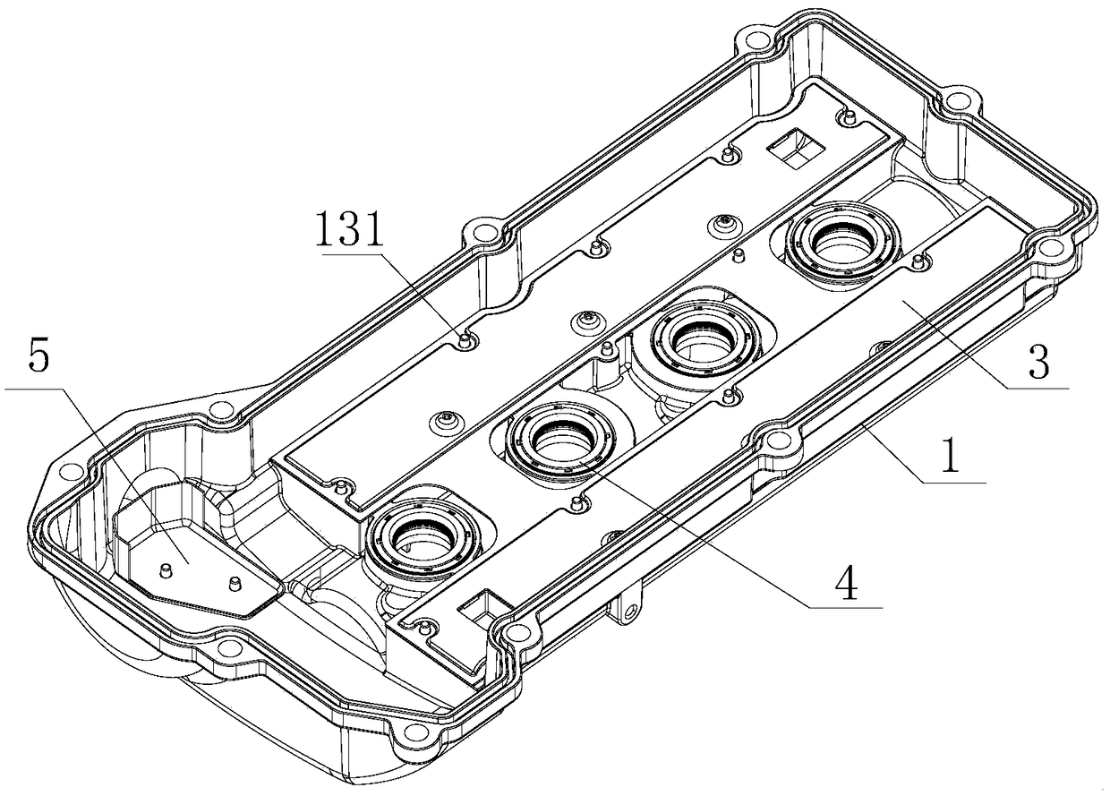
[0028] see Figure 1-8 , the low-noise oil-gas separation type cylinder head cover assembly of the present invention includes a cylinder head cover body 1 with an inner cavity 15, an air outlet pipe 2 communicating with the outer cover of the cylinder head cover body 1 and the inner cavity 15, and an air outlet pipe 2 located in the middle of the inner cavity 15. The labyrinth cover plate assembly 3 and the oil baffle plate 5 located at one end of the inner cavity 15; the outer cover surface of the cylinder head cover body 1 is provided with an air outlet hole 17 communicating with the inner cavity, a PVC valve hole 18 and an oil filler cap hole 19, and the outer cover The middle part of th...


PUM


Abstract

The invention discloses a low-noise oil-gas separation type cylinder head cover assembly. The low-noise oil-gas separation type cylinder head cover assembly comprises a cylinder head cover body provided with an inner cavity, a gas outlet pipe communicating an outer cover of the cylinder head cover body with the inner cavity, a labyrinth cover plate assembly arranged in the middle of the inner cavity, and an oil baffle plate arranged at one end of the inner cavity; the outer cover surface of the cylinder head cover body is provided with a gas outlet communicating with the inner cavity, a PVC valve hole and an oil filler cover hole; a downwards-concave water guiding groove is formed in the middle of the outer cover surface; a plurality of ignition coil mounting bases are arranged in the water guiding groove at intervals; the bottom surface, close to the oil filler cover hole, of the inner cavity is provided with an oil baffle plate mounting base; the inner cavity is internally provided with a first reinforcing rib connected with the ignition coil mounting bases; the end of the first reinforcing rib is provided with a second reinforcing rib connected with the first reinforcing rib, the bottom surface of the inner cavity and the side surface of the inner cavity; and the first reinforcing rib and the side wall of the inner cavity are provided with a plurality of sealing plate mounting bases. The cylinder head cover assembly has the function of flow guiding, liquid accumulated at the top of a cylinder head cover can be effectively discharged, the structural strength is high, theanti-vibration capability is good, the service life is long, and low-cost oil separation can be achieved.

Description

technical field [0001] The invention relates to the technical field of auto parts, in particular to a low-noise oil-gas separation type cylinder head cover assembly. Background technique [0002] With the rapid development of my country's automobile industry, the demand for auto parts is also increasing. Cylinder head covers are widely used in the field of auto parts technology as an automobile engine component. Usually, the cylinder head cover assembly is installed above the cylinder head of the automobile engine to cover the cylinder, isolate the communication between the top of the cylinder head and the outside world, and organize the wire harness. [0003] The traditional cylinder head cover assembly is provided with a groove in the middle, and there are many through holes in the middle of the groove, which are used to install the ignition coil. The inner cavity is equipped with a complicated oil-gas separation structure. When washing the car, the water guide function i...

Claims


Application Information

Patent Timeline
Patent Type & Authority Applications(China)
IPC IPC(8): F02F7/00F01M13/04
CPCF01M13/04F02F7/0065F01M2013/0461
Inventor 石宏伟曾根王坷
Owner 鼎欣吉盛科技(浙江)有限公司
Learn More