Fishing boat stern shaft braking device

A brake device and stern shaft technology, applied in the direction of brake parts, brake types, drum brakes, etc., can solve the problems of long inertia braking time, large damage to reverse braking transmission components, and short braking time. Achieve the effect of less damage to parts, reliable stop and high braking efficiency

Pending Publication Date: 2019-01-08
HUANGHAI SHIPBUILDING
View PDF0 Cites 1 Cited by
  • Summary
  • Abstract
  • Description
  • Claims
  • Application Information

AI Technical Summary

Problems solved by technology

[0004] In order to overcome the shortcomings of the existing fishing boat stern shaft inertial braking time and large damage to reverse braking transmission parts, the present invention provides a fishing boat stern shaft braking device with short braking time and small damage to components

Method used


Image

  • Fishing boat stern shaft braking device
  • Fishing boat stern shaft braking device

Examples


Embodiment 1

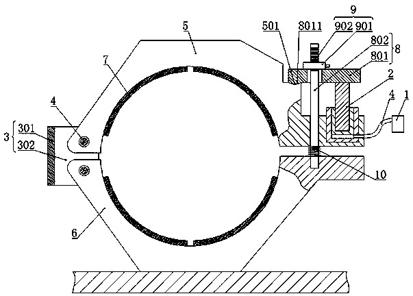
[0018] exist figure 1 Among them, a fishing boat stern shaft braking device, which includes a hydraulic pump station 1, a hydraulic cylinder 2 and a mounting plate assembly 3. Wherein, the hydraulic cylinder 2 communicates with the hydraulic pump station 1 through a hydraulic pipe 11 in a conventional connection manner.

[0019] Such as figure 1 As shown, a fishing boat stern shaft braking device also includes a semi-annular upper hoop 5 and a semi-annular lower hoop 6, the upper hoop 5 and the lower hoop 6 can form an encircling shape. When in use, the upper hoop body 5 and the lower hoop body 6 surround the stern shaft of the fishing boat to achieve braking on the stern shaft of the fishing boat.

[0020] In order to improve the friction force of the upper hoop body 5 and the lower hoop body 6 when braking the stern shaft of the fishing boat, as figure 1 As shown, friction plates 7 are respectively provided on the opposite surfaces of the upper hoop body 5 and the lower h...

Embodiment 2

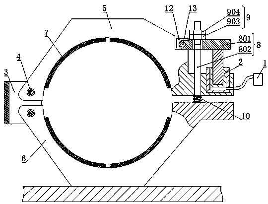
[0029] figure 2 The structure of another embodiment of the present invention is given.

[0030] exist figure 2 Among them, a braking device for the stern shaft of a fishing boat, which is the same as that of Embodiment 1, includes a hydraulic pump station 1, a hydraulic cylinder 2, a mounting plate assembly 3, a semi-circular upper hoop body 5 and a semi-circular The lower hoop body 6, the connecting ends of the upper hoop body 5 and the lower hoop body 6 are respectively connected to the mounting plate assembly 3 through the connecting piece 4; friction plate 7; an actuator 8 is arranged between the locking ends of the upper hoop body 5 and the lower hoop body 6; the cylinder body of the hydraulic cylinder 2 is fixed on the locking end of the upper hoop body 5, and the piston rod of the hydraulic cylinder 2 The upper hoop body 5 and the lower hoop body 6 are tightened or loosened by the actuator 8 . Wherein, its actuator 8 also includes a drive plate 801 and a pull rod 8...


PUM


Abstract

The invention discloses a fishing boat stern shaft braking device to solve the problems that an existing fishing boat stern shaft is long in the inertia braking time and is high in reverse brake transmission component damage. The fishing boat stern shaft braking device comprises a hydraulic pump station, a hydraulic oil cylinder, a mounting plate assembly, a semi-circle upper hoop body and a lowerhoop body. The upper hoop body and the lower hoop body encircle to form an embracing shape. Friction pieces are respectively arranged on the opposite faces of the upper hoop body and the lower hoop body. The connecting ends of the upper hoop body and the lower hoop body are respectively rotatably connected with the mounting plate assembly through connecting pieces. An executing mechanism is arranged between the locking ends of the upper hoop body and the lower hoop body. A cylinder body of the hydraulic oil cylinder is fixed to the locking end of the upper hoop body. A piston rod of the hydraulic oil cylinder drives the upper hoop body and the lower hoop body to encircle or separate through the executing mechanism. The semi-circle upper hoop body and the lower hoop body encircle to form an embracing stem shaft in an embracing shape. Friction braking is achieved between the friction pieces on the opposite faces and a stopping sleeve at the stem shaft. The braking efficiency is high, and component damage is little.

Description

technical field [0001] The invention relates to propeller shaft braking or locking, in particular to a fishing boat stern shaft braking device. Background technique [0002] We know that the propulsion of the ship is realized by the main engine driving the propeller through the stern shaft. Due to the special requirements in fishing operations, fishing boats often need to brake the stern shaft urgently at high speeds, and even need to drive the propeller reversely through the stern shaft to improve the braking efficiency of the ship. Due to the large moment of inertia of the propeller, the inertial braking time of the stern shaft is long, which cannot meet the needs of emergency braking. In addition, the reverse rotation of the propeller also needs to use the reverse function of the gearbox to realize the reverse drive of the stern shaft after the forward rotation stops, which will cause great damage to the main engine and the gearbox. [0003] Therefore, there is an urgen...

Claims


Application Information

Patent Timeline
IPC IPC(8): F16D65/14F16D65/06F16D49/18F16D121/04
CPCF16D49/18F16D65/06F16D65/14F16D2121/04
Inventor 王军武汤晓非李春茂
Owner HUANGHAI SHIPBUILDING
Why Eureka
Try Eureka