Glue pipe for vehicle

A technology for automobiles and rubber hoses, which is applied in the direction of hoses, pipes, pipes/pipe joints/fittings, etc. It can solve the problems of poor fuel resistance and fuel impermeability, large size changes, and small application range, etc., to increase fuel resistance, Effect of reducing deformation and improving safety

Inactive Publication Date: 2019-01-08
扬州尚翔汽车零部件有限公司
View PDF0 Cites 0 Cited by
  • Summary
  • Abstract
  • Description
  • Claims
  • Application Information

AI Technical Summary

Problems solved by technology

[0002] With the optimization of the fuel system of passenger cars, the strict requirements of emission regulations, and the diversification of fuel types, higher requirements are placed on the performance of the fuel system hoses of passenger cars, and the performance of fuel hoses mainly depends on the number of hoses. Layer structure and the type of material used in each layer structure. At present, the structure of the fuel hose is mainly composed of an inner layer, a reinforcement layer and an outer layer. Since the reinforcement layer has only one layer of material, the fuel resistance and fuel impermeability are poor. Some automotive rubber hoses are currently divided into full rubber hoses without a reinforced layer and reinforced rubber hoses with an intermediate reinforced braided layer according to the different pressure resistance. For the former, due to its poor pressure resistance and low strength, the scope of application Relatively small, the latter is generally composed of three layers, the outer rubber layer, the braided layer reinforcement layer and the inner rubber layer. It cannot meet the current people's requirements for this product, so how to design rubber hoses for automobiles has become a problem we have to solve at present

Method used


Image

  • Glue pipe for vehicle
  • Glue pipe for vehicle
  • Glue pipe for vehicle

Examples


Embodiment Construction

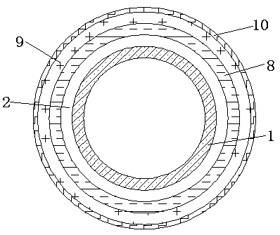
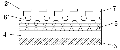
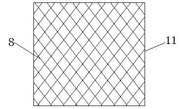
[0017] The present invention will be further described below in conjunction with specific embodiments, wherein, the accompanying drawings are only for exemplary illustrations, and what is shown is only a schematic diagram, rather than a physical map, and cannot be understood as a limitation to this patent. In order to better illustrate the present invention Specific embodiments, some parts in the drawings will be omitted, enlarged or reduced, and do not represent the size of the actual product. For those skilled in the art, it is understandable that some known structures and their descriptions in the drawings may be omitted. Based on The specific implementation modes in the present invention and all other specific implementation modes obtained by persons of ordinary skill in the art without making creative efforts all belong to the protection scope of the present invention.

[0018] see Figure 1-Figure 4 , the present invention provides a technical solution: rubber hose for a...


PUM


Abstract

The invention discloses a glue pipe for a vehicle. The glue pipe comprises an inner glue layer, and is characterized in that a reinforcing layer is arranged on the outer side of the inner glue layer;the innermost layer of the reinforcing layer is arranged as a first chlorinated butyl rubber layer; a fluororubber layer is arranged on the outer side of the first chlorinated butyl rubber layer; a second chlorinated butyl rubber layer is arranged on the outer side of the fluororubber; a fluorine resin layer is arranged on the outer side of the second chlorinated butyl rubber layer; a first silicone rubber layer is arranged on the outer side of the fluorine resin layer; a skeleton layer is arranged on the outer side of the reinforcing layer; and an outer glue layer is arranged on the outer side of the skeleton layer. The glue pipe for the vehicle is simple in structure, prevents the fuel permeation, is excellent in fuel resistance, cannot be corroded by fuel after long-time use, can be used in bad outdoor environment, is higher in high-temperature and low-temperature resistance, meanwhile, can prevent the water, the flame and the fuel leakage, is high in practicability and applicability, and achieves abroad application prospect.

Description

technical field [0001] The invention relates to the technical field of rubber hoses, in particular to rubber hoses for automobiles. Background technique [0002] With the optimization of the fuel system of passenger cars, the strict requirements of emission regulations, and the diversification of fuel types, higher requirements are placed on the performance of the fuel system hoses of passenger cars, and the performance of fuel hoses mainly depends on the number of hoses. Layer structure and the type of material used in each layer structure. At present, the structure of the fuel hose is mainly composed of an inner layer, a reinforcement layer and an outer layer. Since the reinforcement layer has only one layer of material, the fuel resistance and fuel impermeability are poor. Some automotive rubber hoses are currently divided into full rubber hoses without a reinforced layer and reinforced rubber hoses with an intermediate reinforced braided layer according to the different ...

Claims


Application Information

Patent Timeline
IPC IPC(8): F16L11/10B32B1/08B32B27/02B32B15/088B32B15/14B32B15/20B32B25/08B32B25/18B32B25/20B32B25/10B32B15/06B32B33/00
CPCF16L11/10B32B1/08B32B5/02B32B5/26B32B15/06B32B15/14B32B15/20B32B25/08B32B25/10B32B25/18B32B25/20B32B33/00B32B2262/0269B32B2307/206B32B2307/306B32B2307/3065B32B2307/714B32B2307/7265
Inventor 成岗
Owner 扬州尚翔汽车零部件有限公司
Why Eureka
Try Eureka