
Polishing device having pad which has grooves and holes

A polishing device and polishing pad technology, which are applied to wheels with flexible working parts, machine tools with surface polishing, grinding/polishing equipment, etc., can solve the problem that the amount of polishing agent 16 cannot be effectively reduced.

Inactive Publication Date: 2002-10-02
RENESAS ELECTRONICS CORP
View PDF1 Cites 0 Cited by
  • Summary
  • Abstract
  • Description
  • Claims
  • Application Information

AI Technical Summary

Problems solved by technology

However, if the rotation speed exceeds about 20 rpm, this method cannot effectively reduce the consumption of the polishing agent 16 due to the inclination of the liquid surface of the polishing agent.

Method used


Image

  • Polishing device having pad which has grooves and holes
  • Polishing device having pad which has grooves and holes
  • Polishing device having pad which has grooves and holes

Examples


Embodiment Construction

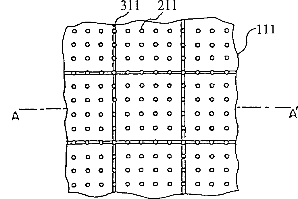
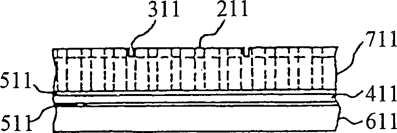
[0050]In the polishing pad as a preferred embodiment of the present invention, the required minimum number of grooves are formed on the polishing pad with holes for holding a polishing agent. These grooves are used to reduce the tight seal and to make the excess loading of the edge part of the semiconductor chip less, so their pitch is several times larger than that of the prior art grooves in FIG. 24 . That is, the grooves of the present invention are not effective in supplying polishing compound to the semiconductor wafer, but are effective in supplying atmospheric air to the holes.

[0051] Except for the shape of the polishing pad, the present polishing apparatus is the same as the prior art shown in Figs. 21 and 22 . Therefore, in the following description, the same serial numbers are used for the same parts as those of the prior art.

[0052] Such as figure 1 with figure 2 As shown, the polishing pad of the first embodiment of the present invention has shallow groov...


PUM


Abstract

Shallow grooves and holes are formed on the surface of the hard layer of the polishing pad used for polishing thin slices. Since the grooves are formed so that no negative pressure is generated between the polishing pad and the wafer, the groove pitch is made several times larger than the hole pitch.

Description

technical field [0001] This invention relates to a wafer polishing apparatus, and more particularly to the shape of the polishing pad in such an apparatus. Background technique [0002] Recently, a chemical-mechanical polishing method (hereinafter referred to as CMP) has been used in processing the surface of a thin sheet such as a silicon wafer for large scale integration (LSI). According to this method, as shown in FIGS. 21 and 22, the wafer surface is polished by using a combination of mechanical and chemical actions. [0003] The polishing device has a rotatable worktable 11, the workbench 11 has a flat surface. The diameter of workbench 11 is about 50 to 100 cm, made of high hardness material. A polishing pad 1 about 1 to 3 mm thick acts on the surface of the table 11 . [0004] In addition, the polishing device also has an object carrier 12 whose shape is adapted to the diameter of the semiconductor wafer 15 . The object carrier 12 is located above the worktable 11 ...

Claims


Application Information

Patent Timeline
Patent Type & Authority Patents(China)
IPC IPC(8): B24B37/20B24B37/22B24B37/24B24B37/26B24D13/14H01L21/304
CPCB24B37/26B24B7/00B24D3/34
Inventor 鸟井康司
Owner RENESAS ELECTRONICS CORP
Learn More