
Coupling self-adaptive robot finger device characterized in that tail end moves along straight line

A robot finger and linear motion technology, applied in the direction of manipulators, chucks, manufacturing tools, etc., can solve the problems of increasing robot control difficulty and programming requirements, increasing control complexity, and inability to couple and balance, so as to reduce control difficulty and structure Compactness, the effect of improving work efficiency

Active Publication Date: 2019-01-11
ANHUI UNIVERSITY OF TECHNOLOGY
View PDF9 Cites 6 Cited by
  • Summary
  • Abstract
  • Description
  • Claims
  • Application Information

AI Technical Summary

Problems solved by technology

The disadvantages of the double-joint parallel underactuated robot finger device are: 1) too many spring parts are used, and the coupling balance between the spring parts cannot be well realized in the grasping process, and the grasping force is too small; 2) the robot During the coupled grasping process of the finger, the end of the second finger segment moves in a circular arc relative to the base. When there is a flat and small object on the table, it is necessary to move the mechanical arm to realize the process of pinching and grasping. additional control complexity
In order to achieve stable pinching at the end of the finger at the height of the object in the final stage of grasping, at present, only the mechanical arm can be used to control the overall position of the robot hand, and the overall position of the robot hand can be continuously adjusted as the fingers are coupled and bent. The height greatly increases the control difficulty and programming requirements of the robot when grasping

Method used


Image

  • Coupling self-adaptive robot finger device characterized in that tail end moves along straight line
  • Coupling self-adaptive robot finger device characterized in that tail end moves along straight line
  • Coupling self-adaptive robot finger device characterized in that tail end moves along straight line

Examples


Embodiment Construction

[0039] The specific structure and working principle of the present invention will be further described in detail below in conjunction with the accompanying drawings and embodiments.

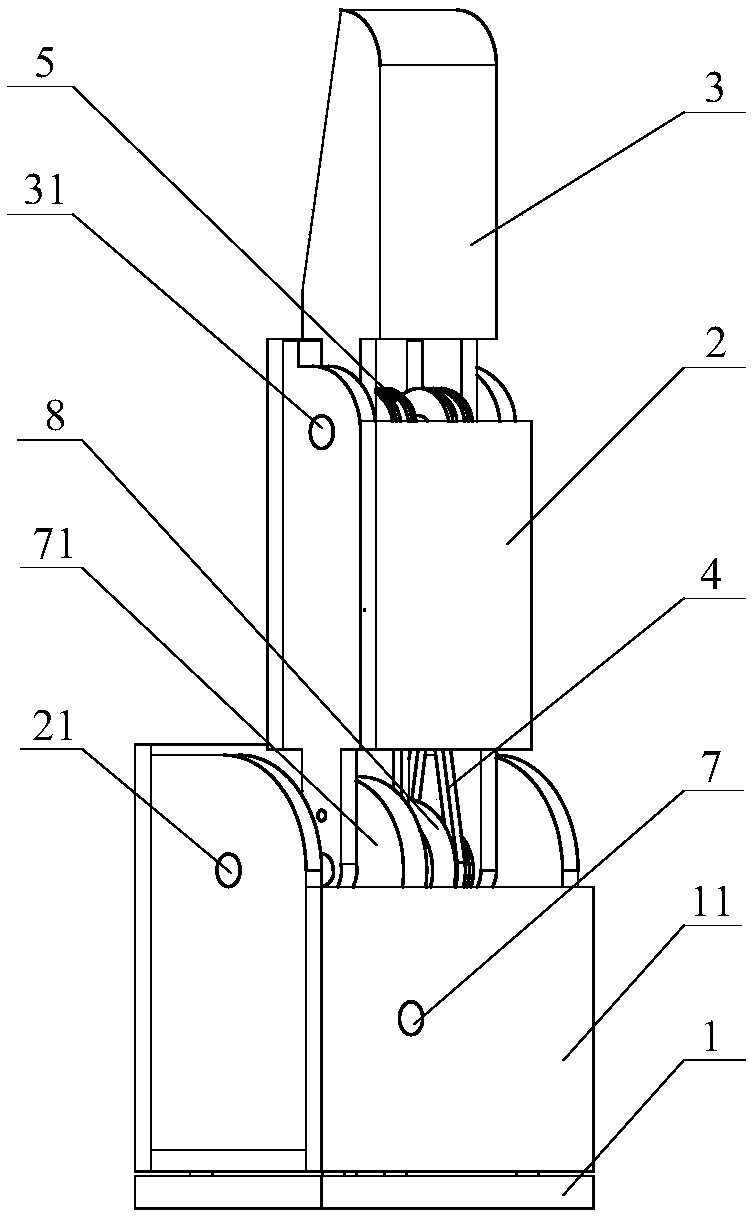
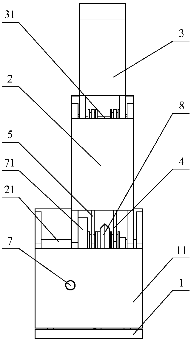
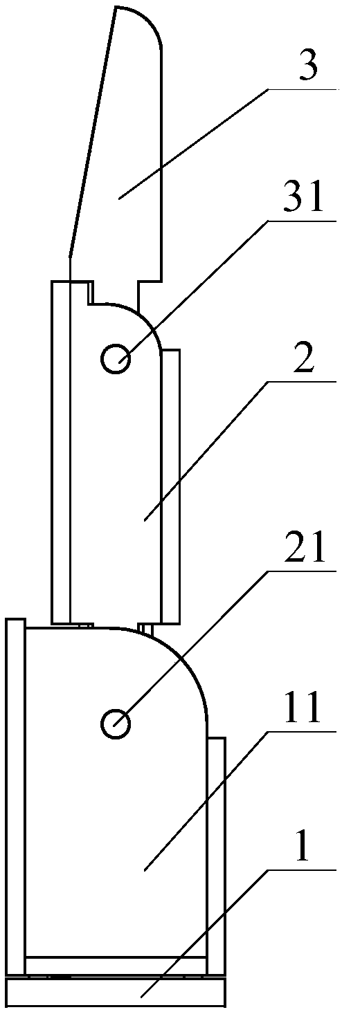
[0040] An embodiment of the coupled adaptive robot finger device with the end of the present invention designed to move along a straight line, such as Figure 1-5 As shown, a coupling adaptive robotic finger device whose end moves along a straight line includes a base 11, a first finger segment 2, a proximal joint shaft 21, a second finger segment 3, a distal joint shaft 31, a first transmission mechanism 4, The second transmission mechanism 5, the third transmission mechanism 8 and the motor 12; the motor 12 is fixed in the base 11; the proximal joint shaft 21 is movably sleeved in the base 11; the first finger section 2 is movable Socketed on the proximal joint shaft 21; the distal joint shaft 31 is movably sleeved in the first finger segment 2, and the center line of the distal joint shaft 31 ...


PUM


Abstract

The invention discloses a coupling self-adaptive robot finger device characterized in that the tail end moves along a straight line, and belongs to the technical field of robot hands. The coupling self-adaptive robot finger device comprises a base, a pedestal, a first finger section, a second finger section, a near joint shaft, a far joint shaft, a motor, three transmission mechanisms, two springparts, a cam, a push rod, a rolling wheel, a stroke increasing mechanism and a poking block. The coupling self-adaptive robot finger device can achieve coupling movement, achieves the effect of pinching an object, can also achieve self-adaptive movement, and achieves the effect of covering and holding objects with different shapes and different sizes. In the stage of coupling movement, the tail end of the second finger section moves along the straight line relative to the pedestal, the coupling self-adaptive robot finger device is suitable for pinching the object on a workbench in a coupling mode, the whole height of a robot hand does not need to be adjusted, the control difficulty of a mechanical arm is reduced, and the working efficiency is improved. The coupling self-adaptive robot finger device adopts an under-actuated move, two joints are driven by one driving device, and no complex sensing and control system is required. The coupling self-adaptive robot finger device is compact in structure, small in size and low in cost, and is suitable for the robot hand.

Description

technical field [0001] The invention belongs to the technical field of robot hands, and in particular relates to the structural design of a coupled adaptive robot finger device whose end moves along a straight line. Background technique [0002] As an important part of the robot, the robot hand is a hot and difficult point in robot research. Some hands are designed in the shape of human hands to imitate the movement of human hands, and some hands are developed for industrial operations, such as industrial grippers, underactuated hands, dexterous hands, and special hands. The underactuated robot hand uses a small number of motors to drive multiple joints. Compared with the fully active control robot hand, each joint is driven by a motor. The underactuated robot hand cleverly uses springs as energy storage elements and transmission mechanism deformation, effectively reducing The control complexity and weight of the entire manipulator, and the motor can be hidden in the base, ...

Claims


Application Information

Patent Timeline
IPC IPC(8): B25J15/00B25J15/12
CPCB25J15/0009B25J15/12
Inventor 杨阳徐向荣张文增
Owner ANHUI UNIVERSITY OF TECHNOLOGY
Learn More