Elevator brake with emergency brake system and working method for elevator brake

An elevator brake and emergency braking technology, which is applied in the direction of brake types, elevators, hoisting devices, etc., can solve problems such as insufficient braking force, failure of braking force, and inability to close and close the brakes, so as to reduce noise and increase braking force Effect

Active Publication Date: 2019-01-11
ZHEJIANG SCI-TECH UNIV
View PDF13 Cites 9 Cited by
  • Summary
  • Abstract
  • Description
  • Claims
  • Application Information

AI Technical Summary

Problems solved by technology

[0004] Electrical problems are mainly due to poor contact or adhesion of the contacts of the control brake, intermittently, causing friction and wear between the brake shoe and the brake wheel, resulting in failure of the braking force
[0005] Mechanical problems mainly include: mechanical jamming causes the brake to fail to close or slow to close after power failure; the brake spring has insufficient pressure due to long-term use, resulting in insufficient braking force; the installation of the armature in the brake is skewed, resulting in wear of the friction brake shoe Seriously, the contact area between the brake wheel and the friction brake shoe is less than 80%, and the braking force is reduced; there is residual magnetism in the core of the electromagnetic coil. At the moment of standing, the brake iron core is stuck and cannot be closed, which is prone to car slipping accidents
[0006] The above problems lead to poor safety and stability of the brake

Method used


Image

  • Elevator brake with emergency brake system and working method for elevator brake
  • Elevator brake with emergency brake system and working method for elevator brake
  • Elevator brake with emergency brake system and working method for elevator brake

Examples


Embodiment Construction

[0037] The present invention will be further described below in conjunction with the drawings.

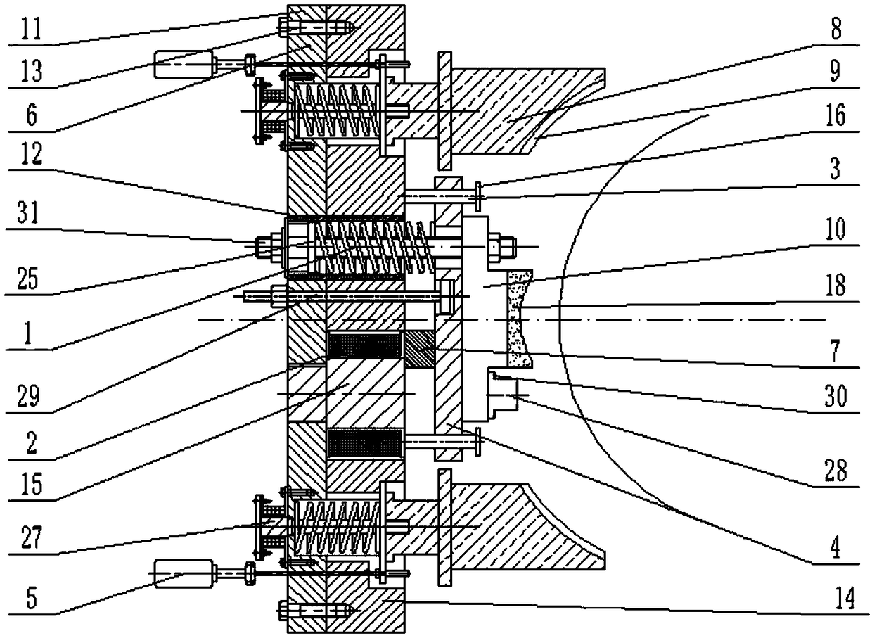
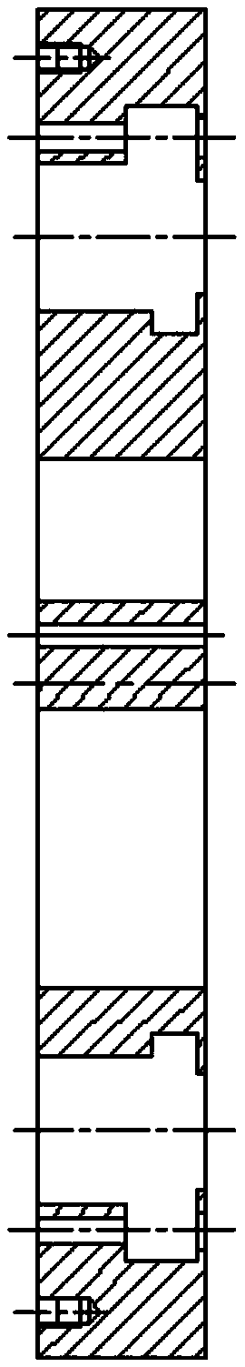
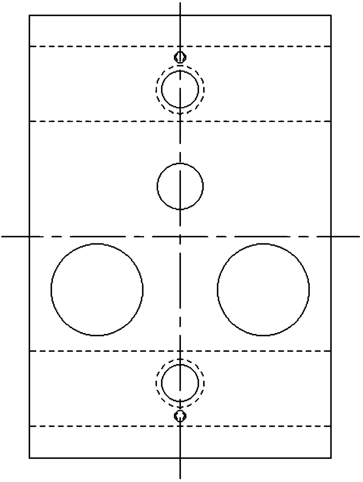
[0038] Such as figure 1 , figure 2 , image 3 , Figure 4 , Figure 5 with Image 6 As shown, the elevator brake with emergency braking system includes brake spring 1, coil winding 2, guide post 3, armature 4, emergency brake assembly 5, manual brake release lever 29, preload adjustment lever 31, and return The assembly 27, the combined support body 6, the tongue plate 10, and the friction brake shoe 18 fixed on the tongue plate 10; the combined support body 6 includes a housing 11, a spring sleeve 12 and an iron core plate 14; the housing 11 is provided with a sleeve Mounting hole one, brake release lever mounting hole one, two brake assembly mounting holes one, two iron core post mounting holes one and two rotating shaft mounting holes one; sleeve mounting hole one, brake release lever mounting hole one, The centers of the two brake component mounting holes one and the two rotating...


PUM


Abstract

The invention discloses an elevator brake with an emergency brake system and a working method for the elevator brake. The elevator brake comprises a brake spring, a coil winding, a guide post, an armature, an emergency brake assembly, a return assembly, a manual brake loosening rod, a pre-tightening force regulating rod, a combined supporting body, a tongue plate and a friction gate tile fixedly arranged on the tongue plate. When a car sliding phenomenon occurs, an emergency brake shoe tightly holds a brake wheel; when elevator maintenance is performed after emergency braking, if a distance between the tongue plate and the brake wheel reaches a threshold value when a capacitive type displacement sensor feeds back the occurred sliding phenomenon, a computer judges that the friction brake shoe needs to replace, otherwise, a barrel on the pre-tightening force regulating rod is manually rotated to increase pre-tightening force of the brake spring. The elevator brake can emergently brake, can determine maintenance time according to data acquired by a ring-shaped pressure sensor and the capacitive type displacement senor, and avoids the trouble that the brake screw needs to manually regulate frequently

Description

Technical field [0001] The invention belongs to the technical field of elevator brakes, and particularly relates to an elevator brake with an emergency braking system and a working method thereof. Background technique [0002] Traditional elevator brakes are generally electromagnetic brakes, and their components are compression springs, brake electromagnetic mechanisms, brake shoes, brake wheels, transmission and adjustment mechanisms, etc. Its main principle is to control the action of the armature by generating or losing the electromagnetic attraction when the electromagnetic coil is switched on and off, so as to achieve the purpose of braking. Today, when elevators are widely used in people’s daily life, people gradually begin to pay attention to the safety and comfort of elevator operation, and the failure of the brake will cause the elevator to slip, top or bottom, so it is necessary to prevent the failure of the brake to ensure the elevator brake The performance is safe an...

Claims


Application Information

Patent Timeline
Patent Type & Authority Applications(China)
IPC IPC(8): B66B5/16B66B5/00B66D5/30F16D66/02
CPCF16D66/022B66B5/0031B66B5/16B66D5/30
Inventor 魏义敏张鹏陈文华潘骏
Owner ZHEJIANG SCI-TECH UNIV
Why Eureka
Try Eureka