Unlock instant, AI-driven research and patent intelligence for your innovation.

Steel grid construction technology based on BIM lofting and three-dimensional scanning

A technology of three-dimensional scanning and construction technology, which is applied in the processing of building materials, construction, building construction, etc., can solve the problems of overall hoisting accuracy, safety and construction efficiency not being significantly improved, inconsistent lifting speed of steel grids, Problems such as the inapplicability of the installation of the steel grid frame, to achieve the effect of reducing labor input, efficient construction work, and saving measurement

Active Publication Date: 2019-01-11
QINGDAO NO 1 CONSTR GRP
View PDF6 Cites 32 Cited by
  • Summary
  • Abstract
  • Description
  • Claims
  • Application Information

AI Technical Summary

Problems solved by technology

[0006] Although the above method can complete the installation of the grid frame in place, there is a situation that the lifting speed of the two ends of the steel grid frame is prone to inconsistent due to the influence of uneven traction force during the overall lifting process of the steel grid frame, which eventually leads to inaccurate installation; The accuracy, safety and construction efficiency of the overall hoisting have not been significantly improved. It is only suitable for the installation and construction of the grid with a flat setting and a relatively high overall rigidity. However, for high assembly accuracy, high installation accuracy, and high installation process monitoring accuracy, The structure is complex, the number of components is large and relatively large, and the installation of steel grid frames with complex and strange shapes is not suitable

Method used


Image

  • Steel grid construction technology based on BIM lofting and three-dimensional scanning
  • Steel grid construction technology based on BIM lofting and three-dimensional scanning

Examples


Embodiment Construction

[0039] The present invention will be described in further detail below in conjunction with the accompanying drawings and specific embodiments.

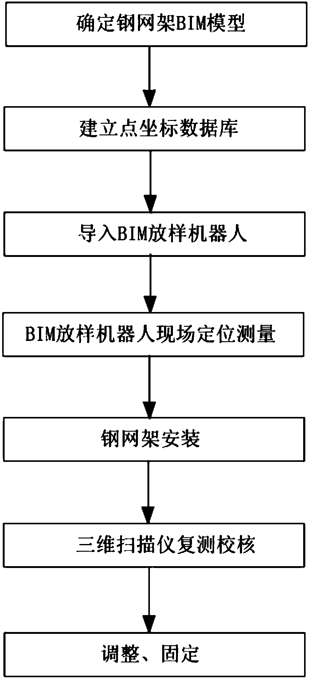
[0040] Such as figure 1 As shown, the steel grid construction process based on BIM lofting and 3D scanning includes the following steps:

[0041] (1) Determine the BIM model of the steel grid:

[0042] The steel grid model is optimized according to the layout principles, clearance requirements and deepening standards, and the BIM model of the steel grid is determined after joint review by professional engineers and design units.

[0043] (2) Establish point coordinate database:

[0044] According to the plane positioning and elevation data, the coordinate points to be set out on site are set in the steel grid BIM model as the reference points, and the number of reference points is more than 2. Then perform data processing on the points in each area, including the coordinate points of the BIM model of the steel grid, the coordinate ...


PUM


Abstract

The invention relates to the technical field of building construction, in particular to a steel grid construction technology based on BIM lofting and three-dimensional scanning. The steel grid construction technology includes the following steps: (1) determining a BIM model of a steel grid; (2) establishing a point coordinate database; (3) importing a BIM lofting robot; (4) carrying out on-site positioning measurement by the BIM lofting robot; (5) installing the steel grid; (6) carrying out re-measurement and examination by a three-dimensional scanner; and (7) carrying out adjustment and fixation. The steel grid construction technology starts from the basic BIM. Then, automatic lofting is carried out on a construction site. Finally, the actual construction structure information obtained bythe three-dimensional scanner through on-site surveying and mapping is compared with the data aggregated by the model. The compatibility of hardware and software, the analysis of lofting accuracy through actual measurement, the multi-professional data sharing and the improvement of the measurement lofting efficiency are systematically combined. The steel grid construction technology has high construction accuracy and short construction period, improves the efficiency of measurement, saves cost, improves the economic benefit, and is worth popularizing and applying widely.

Description

technical field [0001] The invention relates to the field of building technology, in particular to a steel grid construction process based on BIM lofting and three-dimensional scanning. Background technique [0002] BIM (Building Information Modeling), also known as building information modeling, is a new type of computer application technology in the engineering construction industry. , design, construction, operation management and other stages of the whole life cycle process to share and transfer, so that engineering and technical personnel can correctly understand and efficiently respond to various building information, and provide design teams, construction units and construction operation units, including The construction subjects of all parties provide the basis for collaborative work, and play an important role in improving production efficiency, saving costs and shortening the construction period. [0003] With the advancement of construction engineering technology...

Claims


Application Information

Patent Timeline
IPC IPC(8): E04G21/00E04G21/14E04G21/18
CPCE04G21/00E04G21/14E04G21/18
Inventor 张广鹏张涛李堂飞傅积平许海英
Owner QINGDAO NO 1 CONSTR GRP
Features
  • R&D
  • Intellectual Property
  • Life Sciences
  • Materials
  • Tech Scout
  • Unparalleled Data Quality
  • Higher Quality Content
  • 60% Fewer Hallucinations
Learn More